Disclaimer: This tutorial is for educational purposes. The instructions and products discussed are for the creation of homemade games only, or for repairing damaged cartridges for personal use, and should not be used for duplicating and distributing games protected by copyright. I am not responsible for any damage to you or your property – attempt these projects at your own risk!
Nintendo enthusiasts, myself included, know the value of playing a game on the hardware it was designed for, rather than on an emulator. There do exist USB adapters to take your NES controller and make it work with emulators on your PC, and this mimics playing on the real hardware, but it just doesn’t give you that authentic NES experience.
I’m here to show you just how you can have that authentic NES experience without an emulator. I know there are a handful of these tutorials out there, but I had yet to find one that was as comprehensive as I’d like it to be, so I made this one myself.
Table of Contents
Step 1: Prepare your ROM files
Step 2: Choose a board, or find a suitable donor cartridge
Step 3: Choose your memory chips
Step 4: Expand the ROMs and program your chips
Step 5: Wire the chips to the board
– Using an adapter board
– Rewiring by hand
Step 6: Finalize your game
Equipment you will need
You’ll need a few basic things:
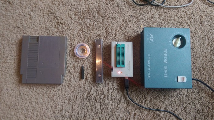
1) Programmer. This is what you use to program the chips the game data is stored on. I got mine on eBay for about $50. It’s a TL866 MiniPro programmer. There’s an updated model, the TL866II Plus, and it seems to work just as well. The TL866 has worked flawlessly for me so far, even after 5 years, and it’s pretty easy to use. There are other more advanced programmers out there, but they run a lot more expensive. If you have one of those other programmers, you’ll have to figure out how to use it yourself (though, if you’re reading this and you already own a programmer, you probably know what you’re doing anyway, nerd).

2) Memory chips. The heart and soul of the NES game. This is where the game data is stored, usually on two separate chips. You’ll typically need at least two of the same size, as most games use two, which are called program (PRG) and character (CHR) ROMs. Some games may only use the PRG ROM.
3) A circuit board. This board is either custom built, or comes from a donor game, and it’s the main component of your game. For using a donor, you’ll want to pick a game that is pretty cheap, or that you don’t care about anymore (please don’t destroy your copy of Megaman 3). You’ll need a specific donor depending on what game you want to make. But I recommend trying to use a new board whenever possible to avoid cannibalizing the ever-dwindling supply of original NES games. I’ll go over some options later on.
3b) Adapter boards. I make these and sell them on my store page. They make rewiring the EPROMs/flash chips a lot easier. I’ll go into more detail about them later on and the benefits there are by using them – you might not need them, but if you have to rewire anything, it’ll help out a lot! You’ll need one for each ROM (PRG and/or CHR, where applicable) if you decide to use them.

4) EPROM eraser. This is for erasing your EPROMs. You’ll need this to fix something you programmed at some point, or you’ll have to clear the chips you order since they’ve probably got something written on them. If you end up using flash memory chips, you don’t need this!

5) Miscellaneous hardware. At the bare minimum, you’ll need solder, and a soldering iron. You might need some extra wire – I use 28 gauge. You’ll also probably want a screwdriver that can open NES cartridges (called a Security Bit), or if you’re cheap and really like making things harder for yourself, you can try to use pliers to remove the screws. But you really should just get one. I used to melt the ends of old mechanical pencils to try to make a mold of the screw and use that. Not worth it.
If you do go and buy the security bit, be sure to get the 3.8mm size, and not the 4.5mm. (Though, if you’re planning on making Genesis games, those use 4.5mm screws. These bits usually come in a pack).
So now that you’ve got an idea of the supplies you’ll need, let’s get cookin’ (or rather, brewin’) some good ol’ NES games.
Step 1: Prepare your ROM files
A forewarning: the games you’ll be able to make are games that are in your region’s video encoding format – NTSC or PAL. If you try to make a game that’s formatted for a different region, you’ll probably get some graphical glitches at best, or a completely non-working game at worst. Generally, NTSC encompasses North America and Japan, and PAL is everywhere else. I’m sure there are exceptions, so please look it up if you’re unsure. Making PAL games for your NTSC console or vice-versa will give you mixed results. See if you can find a version of the game you want to make that’s correctly formatted for your region.
With that out of the way, the first thing we should do is get your ROM file ready (most likely in the .nes format) to get some basic information to use in the next step. Some NES games use only one ROM chip, some use two. You’ll either have a PRG ROM, or a PRG and CHR ROM to take care of. PRG ROMs carry program data, and CHR ROMs carry graphics data.
Your single ROM file contains both PRG and CHR data (if your game uses both) and usually a header with information about the ROM. We need to strip the header off, and split the game into PRG and CHR components. The files we get out of this process, and their sizes, are important for the rest of the tutorial. There are two main ways I’ve used to prepare the proper PRG and/or CHR files.
FamiROM
FamiROM is a great tool that takes care of a lot of steps all at once. But for now, we’ll just be using it to get information about our game. To load up your ROM into the program, just click “Load ROM” and locate it. Then, you should get a window with a bunch of details about your game.
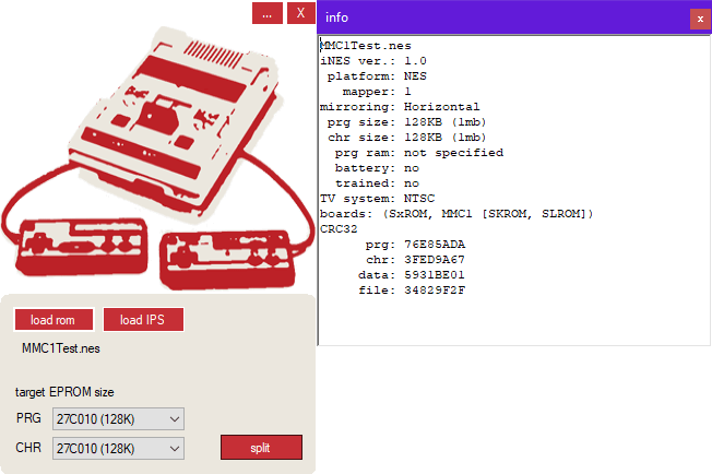
Note the “prg size” and “chr size” fields on the right (Program and Character). Keep this in mind for later – and don’t close this window just yet, we’ll be revisiting it later on.
ReadNES3
Note that, especially if you are a beginner, I recommend using FamiROM over ReadNES3. But I will detail how to use it here, just in case.
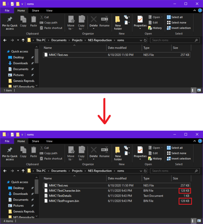
The other tool I’ve been using for a long time now (only recently supplanted by FamiROM) is ReadNES3. It’s very easy to use – just drag and drop your ROM file on top of the ReadNES3 application (doesn’t need to be in the same folder), and the ROM will be split into it’s PRG and CHR components (sometimes along with a header), and placed the folder your ROM is located in. Here’s a before and after screenshot of an example ROM that has both PRG and CHR components.
Note: You need to do this even if you know you only have a PRG component of your ROM file, because you need to make sure you strip the header off of the ROM file.
Note the size of your game’s PRG (Program) and CHR (Character) files. They should be some power of two. Keep these sizes in mind for later. If your game only has a PRG component, you’ll get a CHR file that’s 0 KB, which you can ignore.
Ok great, the first step is complete, now let’s proceed to find a way to put this ROM file on a physical board.
Step 2: Choose a board, or find a suitable donor cartridge
This might take some trial and error, but it’s very important to prevent headaches later on, so pay attention!
NES games were produced spanning nearly a full decade, so it’s natural that the games both made technical leaps throughout its lifetime. For example, games like Balloon Fight don’t take up nearly as much space as a game like Super Mario Bros. 3 does. Also, ROMs can come in many different sizes, which require different PCB layouts with different supporting circuitry. As an example, a game like Balloon Fight doesn’t use the same board type (or even use the same kind of ROM chip) as a more complex game like Super Mario Bros. 3 does.
This, of course, means you must choose a compatible board or donor cartridge for the game you wish to make. The first thing you can do to check what kind of board to use is the information provided by FamiROM. Let’s look at the information of our test ROM again.
Under boards, it lists “SxROM, MMC1 [SKROM, SLROM])”. This means you can, in general, use boards that come from the SxROM “family” of boards (where the lowercase ‘x’ stands for other capital letters). FamiROM specifically calls out SKROM and SLROM as suitable board types – I haven’t run into any problems with these suggestions, but it doesn’t hurt to verify them yourself.
Personally, I’ve relied on the amazing website NesCartDB for determining the kind of board I need to use. This website is extremely detailed and a very powerful tool. If you don’t know what kind of board your game requires, or you want to double-check FamiROM, the first thing to do is try to find your game on NesCartDB using the search function. There are profiles for pretty much all NES (and Famicom!) games out there, and each page has loads of information about each game.
IMPORTANT NOTE: NesCartDB is hosted on a private server. Sometimes the website goes down from time to time for various reasons – as of this writing, it is not active. Luckily, a kind person recently hosted a stripped-down version of the site at NesCartDB.com, or the internet archive has saved an old version of the website – it’s a bit trickier to navigate, but it works in a pinch. You can also try looking at the Bigass NES Mapper List and find games that have the same characteristics as the game you want to make. I’ve heard of some misinformation on the list but it seems pretty accurate.
Note that NesCartDB won’t have every game you can make, so if you have a homebrew or some other game like that, you’ll have to find out your ROM information from wherever you got it from. If FamiROM doesn’t give you that information, I know Romhacking.net for example usually has good information about what kind of hardware is necessary for the game.
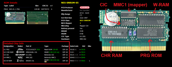
So for example, lets say for the MMC1Test ROM I have above, NesCartDB tells me this this game works on an SLROM board, very common for the MCC1 mapper chip. This information shows up on the right side of the page.
So, I need either a custom SLROM board, a North American SLROM donor cartridge. Looks like FamiROM was right! This is a good point to try to decide what kind of board you’ll be using.
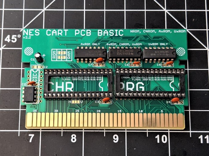
Using a custom PCB
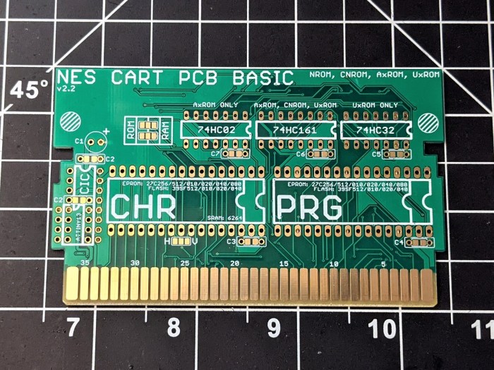
I offer three custom boards – one for games with discrete mappers (NROM, CNROM, AxROM, and UxROM), one for MMC1 games (SxROM), and one for MMC3 games (TxROM). Note that the lowercase ‘x’ in these board types can be replaced with other various capital letters (i.e. AxROM = ANROM, AMROM, and AOROM). Here’s a small gallery of some of my offerings:


Neat, right? I think they look downright beautiful myself, winky emoji. Using custom PCBs is great for preserving NES games since you won’t have to cannibalize another cartridge, even if those donors are crappy cheap games. They won’t be around forever, after all! The only real downside is that you have to provide your own cartridge shell, but there are plenty of them out there that you can use – and honestly, I like using new ones simply because it means I don’t have to remove any dumb labels, or worry about any blemishes on these 30+ year old plastic shells.
You might have noticed that there are a lot of sockets for different parts. Fret not! I have written a guide for you that goes over what other parts you will need for each board. You can find them in the menu bar, or use these links:
Discrete Mapper Guide
MMC1 Mapper Guide
MMC3 Mapper Guide
I also offer the boards on my store page with parts kits included to take all the guesswork out of it. I’d recommend opening the guides up for following along later, because you’ll need to skip ahead to Step 3 to find out how to get your ROMs on memory chips to put on this board first! If you end up using a custom board, go ahead and go to Step 3. Otherwise, if you use a donor, continue on.
Using a donor cartridge
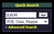
So, back to our example ROM. Remember that we found it was housed on an SLROM board. So, on NesCartDB, all I have to do is go to the search bar on the left side of the site, change the dropdown menu to “PCB, Class, Mapper”, and search SLROM.
Now that’ll bring up a big list of games that use the SLROM board type. I need to find a good, cheap, donor cartridge to use, that’s from the United States. How about Hoops? That’s a great bargain-bin game. I get that in like every lot of NES games I buy off eBay. Conveniently, I have one in my collection to use as a donor. I grab it off my shelf, and open it up and find out… that it’s actually an SL1ROM board! What gives?
Let’s look at the entry for Hoops. It says SLROM… but wait, what’s that “More Profiles” box up there?
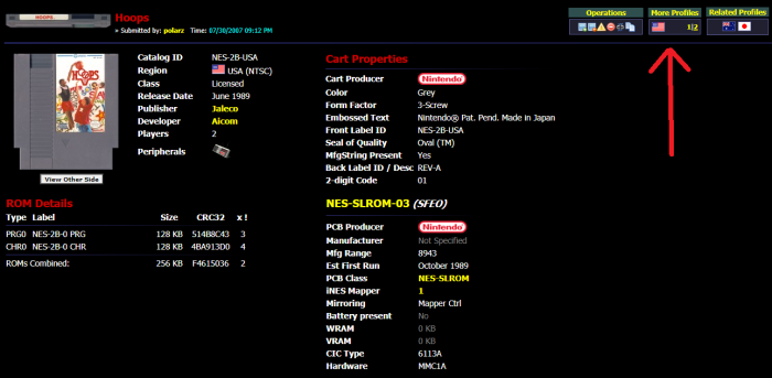
Let’s click on the other profile.
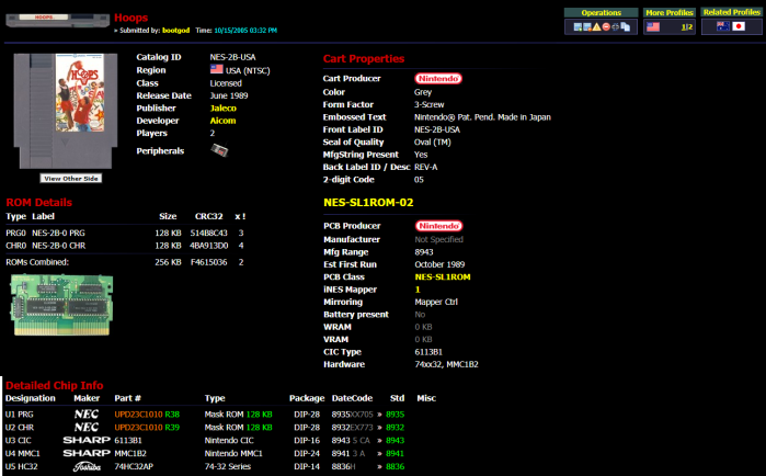
Ah! There’s the problem. Hoops comes in both SLROM and SL1ROM. The two boards are very similar – you might even be able to get away with using the SL1ROM board for the SLROM game, actually, but for the purposes of this tutorial, I’m going to avoid going into that amount of detail. So what we’ve learned is that some games can come in different board types – similar for sure, but slightly different from each other (you’re not gonna find a game that comes in both TLROM and SLROM, for example). When you pick out a donor game, and you don’t have it in front of you yet, it might be a good idea to check all the profiles to see if you might get a different type of board than what you need.
Since my copy of Hoops is SL1ROM, I’m not going to use it. Back to the shelf it goes. Let’s go back to the search results. I see another pretty common game on the list – Golgo 13: Top Secret Episode. Now, when I check all the profiles for this game (there are six in this case), they all come up as variants of SLROM. And sure enough, when I check my own copy of Golgo, it has an SLROM board. Neat!
Now, a final step before declaring victory. Remember back in Step 1 when we found the size of our PRG and CHR files? Look at those again. In my example, the sizes are 128 KB each. Now, lets compare that to the donor game I picked, Golgo 13: Top Secret Episode. Look at the sizes of the ROMs on the bottom of the screen where the chip information is posted (boxed in red).
Note that the ROM size is constant across all profiles of the game, so no need to check them all.
If your donor ROM chips are as large or larger than the game you want to make, you’re good to go – this donor board can handle your game, and you can skip to the next step. Golgo uses 128 KB for both, which is the same size as my game’s files, so I’m good! If these numbers are smaller than your ROM files, don’t fret just yet, you still might be ok. Let’s say, hypothetically, Golgo was listed with 64 KB ROMs, for whatever reason. Even though that size is smaller than what we need, the board itself might still be able to handle our 128 KB files.
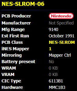
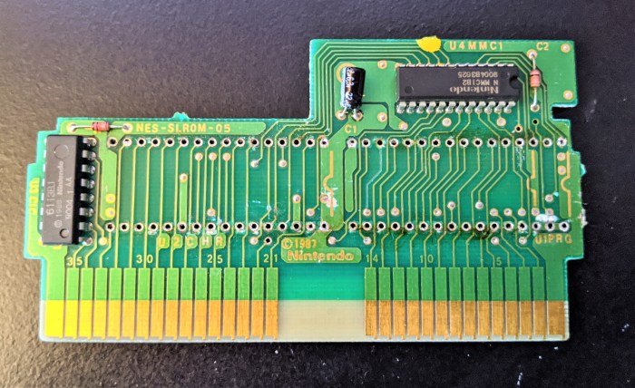
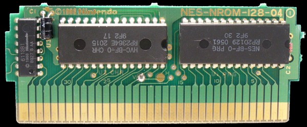
Note the exact board type for your donor in the middle of the screen (boxed in blue above). In this case, it’s NES-SLROM-04. The last two numbers are what matter here. Go to the top bar of the website, where it says “PCBs” (boxed in purple above). When you click that, you’ll be taken to a page that has all of the PCB classes, with a bunch of information on them. Type your exact PCB class name into the search bar on the left. So again, for this example, I type “NES-SLROM-04”. This will bring up that board’s properties.

Check the sizes for the ROMs on the right. These are the maximum ROM sizes you can have for the sockets on this particular board. If these sizes are the same or larger than your ROM files, then you can go ahead and use this board as a donor, and skip to the next step.
If they aren’t, well, then sorry to say you’ll have to start the search over again, but this time with a bit more precision. Let’s assume for a second that we have an example game that has a PRG ROM that’s 256 KB instead of 128 KB, so we’d need to pick a different donor cartridge that can handle the larger size. Click the generic PCB class link on the left side under the “PCB Tree” (boxed in purple above). In my case, that’d be the “NES-SLROM” link on the side. This will bring you to a page with all the different variations of your PCB Class.
Scroll through the variations, and note the max ROM sizes for each board. Sometimes, there will be variations of the board that have higher maximum ROM sizes than others. I can see that for SLROM, there exist a few that go up to 256 KB for the PRG ROM, whereas most go to only 128 KB. Those variations are NES-SLROM-03 and NES-SLROM-06.
See in the red boxes that the size can go up to 256 KB for these boards? So we’d have to find a game that uses one of these two variants for the hypothetical larger game. If you click on the specific variation (boxed in blue above) it will take you to a list of games that use that specific PCB. So find a game from that list to use instead. Remember to check all the other profiles of the game to make sure the PCB class is the same!
But what if my game is a rare board type, and the only donors available are expensive?
You might be out of luck, at least as far as donor carts go. If you can’t find a suitable donor board for your game listed in the results of FamiROM, then you’re stuck, unless a custom PCB exists for you to use or if you’re ok with spending a lot of money on a donor cartridge that you might end up damaging. Games that use the MMC5 mapper come to mind – all of those games are usually quite expensive. Sometimes you can use a Famicom board with a converter (Famicom games have 60 pin cartridge edges, NES games have 72 pins). But maybe there’s someone else online who figured out a way to make your game already using a donor, or maybe there’s a Famicom board that is cheaper – Dr. Google will be your friend there. And of course, there are always flash carts for you to use!
Ok, now that that’s over with, we can get onto the next part – picking out our EPROMs to program.
Step 3: Choose your memory chips
EPROM stands for Erasable Programmable Read-Only Memory. Basically, it holds information (your ROM file) that you can program to the chip, which can be accessed later on by the NES. The data is “burned” into the chip, and can only be cleared by UV light (which is what the little window is for). The other kind of chip you can use is Flash Memory. These chips are reprogrammable without using the UV light, and are generally newly made parts, as opposed to the UV EPROMs.
But why can’t I just reprogram the chips that are already on my donor board? Because they’re one-time programmable! Once you’ve programmed those specific chips for the first time, you can’t change the code.
EPROMs and Flash are functionally used in two different main modes – read and write. We only write to the ROM when we program them, and read the rest of the time. Hence, the “Read-Only Memory” part of EPROM. On these devices, there are a set of “address” pins (A0, A1, etc.) and, in our case, eight data pins (D0, D1, etc.). During the write sequence, a specific address is called out, and a byte of data is output onto the data pins by the programmer, which is then burned into memory at that exact address. When reading the chip, the NES requests an address to read the data on the ROM – the data that was written at that address during the program sequence. That data is output onto those data pins from the memory chip for the NES to use. The mode that the EPROM or Flash is operating in is determined by the Chip Enable (/CE), Output Enable (/OE), and Write Enable (/WE) pins.
So, there are two different types of EPROMs that are generally used for NES games – a 28-pin version, and a 32-pin version. Which should you use? Well, the biggest restriction is the size of your ROM files. The 28-pin EPROMs only hold up to 64 KB. If your game is larger than that, you’ll need to use a 32-pin EPROM. Here’s a list of commonly used EPROMs, and their characteristics.
| Size (Bytes) | Size (Bits) | Chip Name | Top Address | Pin Count | Rewiring? |
| 32 KB | 256 Kbit | 27C256 | A14 | 28 | No |
| 64 KB | 512 Kbit | 27C512 | A15 | 28 | No |
| 128 KB | 1 Mbit | 27C010 | A16 | 32 | Yes |
| 256 KB | 2 Mbit | 27C020 | A17 | 32 | Yes |
| 512 KB | 4 Mbit | 27C040 | A18 | 32 | Yes |
| 1 MB | 8 Mbit | 27C080 | A19 | 32 | Yes |
If you weren’t aware, a byte is equivalent to eight bits. The ROM files we found above are reported in bytes. The EPROMs we’re picking, however, have names related to how many bits they can contain. Since these EPROMs all output data on an 8-bit bus (eight separate data pins), we can think of the address pins (A0, A1, etc.) as which byte is being requested from the NES. In fact, if you take the 2 and raise it to the number of address pins on the chip, you’ll find that it’s equivalent to the total size of the chip in bytes. Each additional address pin doubles the amount of data that can be stored on the chip.
As I mentioned previously, the largest size of a ROM file that a 28-pin EPROM can hold is 64 KB. The benefit of the 28-pin EPROMs, for donor cartridges specifically, is that you don’t have to rewire anything when you use them (unless you’re using the UNROM board type). If you use any of the 32-pin EPROMs on a donor cartridge, you’ll have to do some rewiring to make it work properly, but it’s nothing too difficult.
A while back I bought a bunch of the 64 KB and the 512 KB EPROMs on eBay (27C512 and 27C040). As far as I know, there aren’t any NES games larger than 512 KB (other than some specific homebrews/hacks), and last I checked ‘080’s are kind of pricey. But you can use them if you want to, as they can also be easily used for some smaller SNES games.
Using New Flash Chips
The alternative to the EPROM is the Flash Memory I mentioned earlier. You can use the 39SF010, 020, or 040. Their sizes are the same as their EPROM counterparts. But, as with the EPROMs, I usually just get the ‘040s. You can find these devices new on many websites, like Digikey or Mouser. This is what I use on ALL of my games nowadays (on custom PCBs). The UV EPROMs are old parts that are usually removed from existing boards, erased, and cleaned up. Sometimes you can get defective parts.
Remember – pick a memory chip that is at least as large, if not larger, than each of the PRG and CHR components of your game. Now head onto the next step so we can finally program the game!
Step 4: Expand the ROMs and program your chips
Note that anytime I say “EPROM” in this section, you can also do the same for the Flash Memory. It’s just easier to stick to one device when describing the process.
Ok, back to the ROM files for CHR and PRG. We gotta take care of some business before proceeding. For good measure, we’re going to fill the EPROM up entirely if the game is less than the maximum capacity of the EPROM.
When I say “expanding the ROM” I mean specifically duplicating the ROM and stitching it together to fill up the chip. So a 128 KB ROM on a 256 KB EPROM would need to be doubled. The reason we do this is pretty simple. When you put your 128 KB ROM onto a 256 KB EPROM, for example, the most significant address pin (A17 in the case of the 256 KB EPROM) is only programmed while being a 0. This is because the first half of the 256 KB EPROM is programmed with your ROM, and then since no data exists on the second half of the memory, the programmer doesn’t bother putting anything there. If during gameplay, that top address pin goes to 1 for whatever reason (maybe some noise gets on the line, or you left the pin disconnected from something, or the board type you’re using routes that line somewhere problematic), the EPROM will have no data to load, and will just simply stop playing the game. If we duplicate the ROM to fill the entire EPROM, then no matter what that top address pin is, either 0 or 1, the NES will read the same data.
Note that you don’t need to do this if you tie the unused address pins to GND to keep them at logic 0, but I’m not going to make the tutorial overly-detailed and discuss each and every situation and the wiring required for it, and duplicating the ROMs is an easy enough task anyway! This step is only necessary if your EPROM is larger than the ROM’s CHR or PRG file. You can do this automatically using FamiROM, or if you used ReadNES3, you can do it manually using command prompt.
Using FamiROM to prepare your ROM file(s)
Let’s look at the FamiROM information we had earlier again.
On the bottom left, you’ll see “target EPROM size”. Pick the size of EPROM (or Flash chips) in the drop-down menu that you’ll be using. Once you do that, just hit “split” and FamiROM will remove the .iNES header, split it into PRG and CHR components, and automatically create an expanded version of your ROM(s). Let’s say I wanted to use 27C040 chips for my PRG and CHR ROMs. This is what will show up in the folder.

You’ll see the EPROM name, as well as how many times it was duplicated (x4) is in the file name. That’s it!
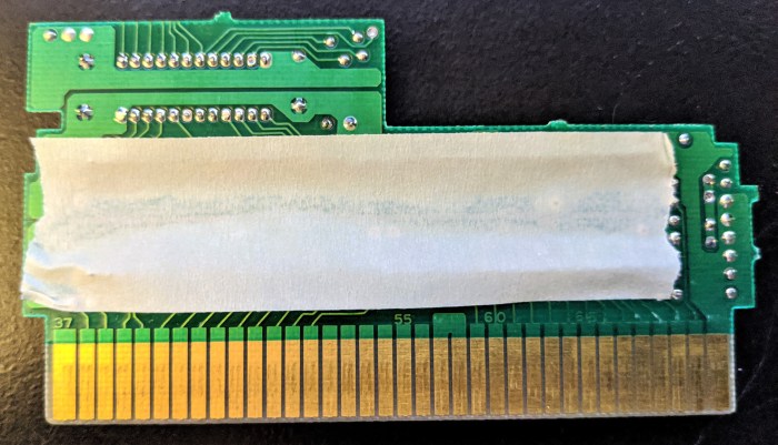
Now, it’s time to program the ROM. I won’t go into too much detail here, you should be able to figure it out! Just plop the EPROM in the programmer, load up your CHR or PRG file, and program each chip. Then put some tape over the window to protect the data on it from getting randomly erased by stray UV rays from outside or something, and mark which EPROM is which.
So, you’ve got your PRG and possibly your CHR ROM ready to go. Now we’ll go into how to install those ROMs onto your board. Skip ahead to Step 5.
Using Command Prompt to prepare your ROM file(s)
Only do this if you’re not using FamiROM. All we need to do is duplicate the .bin files generated by ReadNES3 until they’re large enough to match the size of the EPROM they are going on. This can be achieved by a simple line of code run in command prompt (press Windows+R, type “cmd” and hit “OK”).
First, make sure the command prompt is working in the folder that contains your ROM files. You can use the “cd” command to change the directory. Here’s an example of what I would type in:
cd C:\Users\Nick\Documents\
Just fill in the directory where your ROM is located. Your directory should switch to that on the next line.
The test ROM I’ve been using has a size of 128 KB for both CHR and PRG files. Let’s say I wanted to put the CHR component on a 256 KB EPROM (like the 27C020). We do this with the following line of code:
copy /b MMC1TestCharacter.BIN + MMC1TestCharacter.BIN MMC1CharacterFill.BIN
The “copy” command, obviously copies the data, and “/b” is to denote that the data is in .BIN format. The line of code essentially doubles “gameProgram.BIN” and stores it into the file “gameProgramFill.BIN”.
Let’s say I also have an EPROM that is 4MBit (512KB) that I want to put my 128 KB PRG ROM onto. Instead of doubling it, I quadruple it.
copy /b MMC1TestProgram.BIN + MMC1TestProgram.BIN + MMC1TestProgram.BIN + MMC1TestProgram.BIN MMC1ProgramFill.BIN
Now, compare the sizes of the PRG and CHR files, and the sizes of your EPROMs. They should be the same now after expanding.
Now, it’s time to program the ROM. I won’t go into too much detail here, you should be able to figure it out! Just plop the EPROM in the programmer, load up your CHR or PRG file, and program each chip. Then put some tape over the window to protect the data on it from getting randomly erased by stray UV rays from outside or something, and mark which EPROM is which.
So, you’ve got your PRG and possibly your CHR ROM ready to go. Now we’ll go into how to install those ROMs onto your board.
Step 5: Wire the chips to the board
Note that if you’re using a custom board, you shouldn’t have to rewire anything! You should just be able to plop your programmed ‘PROMs perfectly in their pertinent place! Wow, what an easy step! Don’t forget to put the other necessary parts on your board, too! Skip to Step 6 if you’ve got a custom board. But if you’re using a donor, you’ve got some more work to do.
Nintendo used a standard pinout for their chips that were 28-pins (except UNROM games), which means we can place those EPROMs directly into the existing sockets if you take the old chips out. (I do not know of any compatible commercially available Flash Memory chips that have only 28-pins)
For the 32-pin sockets, we need to do some extra work. You might have noticed that some original NES boards have 32-pin sockets, but only have 28-pin chips, so the top four pins are unused. That 32-pin socket’s bottom 28 pins (pins 3 through 30) are the standard 28-pin layout. Unfortunately, standard 32-pin memory devices don’t match that exact pinout, so using standard chips means you have to rewire some of the pins to put the signals in the right places.
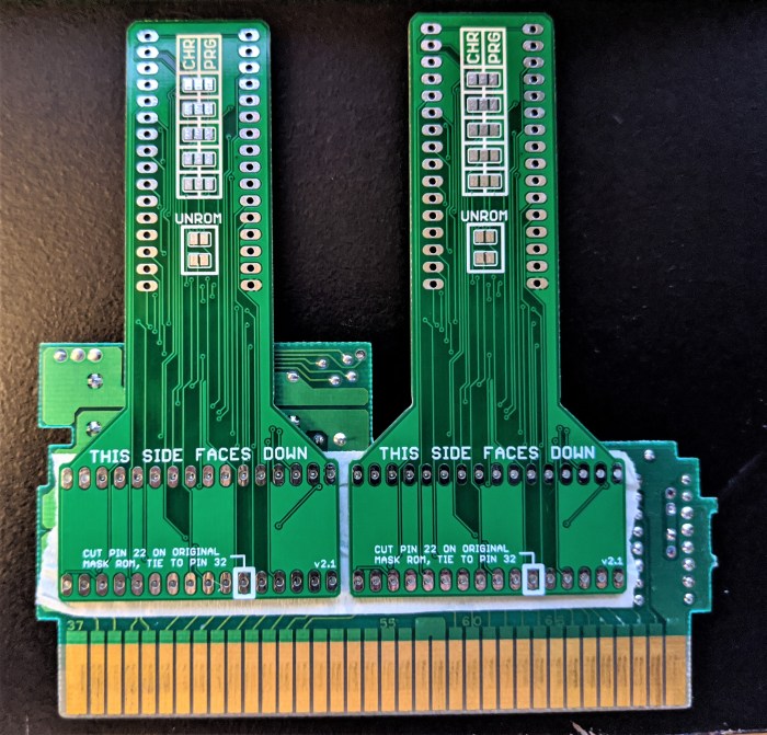
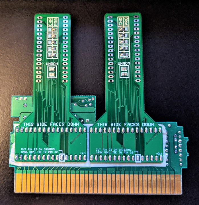
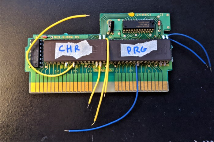
There are two ways of doing this. You can either use your own wire, or use my adapter boards. The boards I have do all the rewiring for you, and has the added benefit of letting you make a game without removing any of the original chips. Removing these old ROM chips is kind of a pain, which is why I made these boards. I’ll go over each method.
Using the adapter boards
If you want to purchase these boards, visit the store page!
This adapter board is made specifically for Nintendo-produced boards with 32-pin sockets, and they DO fit on UNROM boards that have 28-pin sockets as well. You might have problems getting the adapter to fit on Konami-made or other third party boards, so please check before you start. It also won’t fit on boards like NROM or CNROM, which only have 28-pin sockets. But, as I’ve mentioned, if you’re making a game like that, that has 28-pin sockets, you don’t need to rewire anything anyway, so you can simply just take out the existing ROM chip and place your own 28-pin EPROM in.
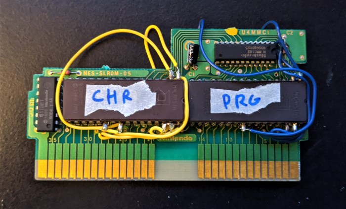
Anyway, we’re going to put the adapter boards on the existing pins sticking out of the bottom of the board. We want the board to sit flat against the board as much as possible, to make sure it fits in the cartridge well, so we need to trim the pins on the other chips as close to the board as possible. Here’s an example for an SLROM board that will house my test ROM.
Note that the pictures used in this section are for a previous version of the adapter board – the new ones will also have solder pads to select between EPROM and Flash.
After you trim the pins, you should be able to lay the adapters flat against the board. You might have noticed that there are some vias filled with solder. This can cause some problems if the exposed solder pads on our adapter board touch the solder on the board. It probably won’t happen, but better safe then sorry. If you’re careful you can avoid them by keeping the adapter a bit above the board, but to make it easy you can put some tape down on top of the pins and push the adapter down on top, creating a barrier between the board and the vias.
Note 1: If your board has a 32-pin socket, but only a 28-pin ROM on it, you’ll have to add four wires to connect the unused donor cartridge sockets and the adapter board sockets. Just strip a wire back and heat up the existing solder, and push it through so that you can access it on the adapter board. After you’ve soldered the backside, add some solder to the topside and trim away the extra wire.
Note 2: If you’re using a UNROM board, which only has a 28-pin ROM on it, you can still use the adapter. Just make sure the adapter board pin 3 sits on ROM pin 1, and adapter board pin 30 sits on ROM pin 28. Check out the picture below (view from the backside) to see which pins to leave alone. You might have to trim off some of the plastic to get the board to fit in the cartridge again, but I haven’t had too much trouble fitting it in afterwards.
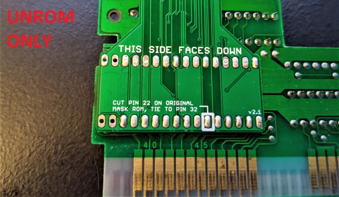
Now, like the above picture suggests, you’ll want to solder the pads and make sure enough solder goes down into the hole to cover the pins. Also, on each adapter board you’re using, be sure to solder the top set of 5 pads on the back to the correct positions depending on if it’s a PRG or CHR ROM. Just add a solder bridge between the middle pad and the left or right depending on what kind of ROM it is. Note that if this is for a UNROM board, you must solder the PRG side as well as bridging the two extra solder pads.
Also, make sure you solder the correct direction for using EPROM or Flash (for new revisions of the adapter boards – not shown in the pictures below).
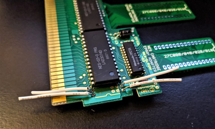
Finally, flip the board over, and cut pin 22 on both of the original ROMs. Make sure the pin doesn’t connect to the board anymore.
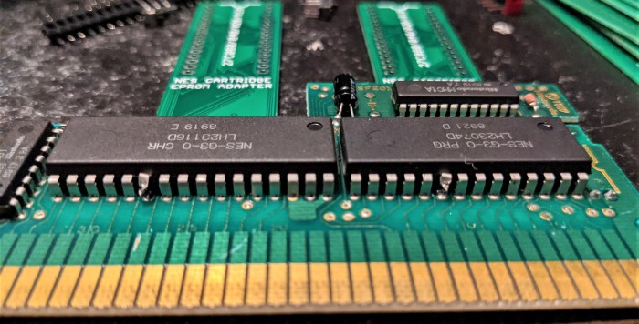
Solder a wire from each pin 22, to pin 32. This will disable the original ROM by tying the /CE pin to 5V, without requiring you from taking it out of the socket.
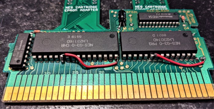
Now we can solder our own EPROMs into the sockets on our adapters.

Now, all the wiring is taken care of! Move on to the last step to finish up.
Rewiring by hand (with EPROMs)
Again, this is only for 32-pin devices, as the 28-pin ones don’t require rewiring (except UNROM – keep reading if you’ve got a UNROM game to make). First, we need to remove the old ROM chips. If you can’t tell which chip is which, look on NesCartDB. They do a good job of letting you know which chips are what. You can also look on the board itself, the ROMs should be marked as such. Be careful – many times the RAM chips look the same as ROM chips. Don’t remove any RAM!
There are a few methods you can go about doing to removing your ROM chips. The easiest way to remove these is to use a vacuum desoldering tool, that is, a soldering iron connected to a vacuum. These are pretty pricey, so I don’t necessarily recommend getting one for this. I use a pump desolder tool. I bought this model, and it works well enough. It’s a bit annoying to clean sometimes though. You can also try using some copper wick and removing the solder that way, but I don’t recommend it as the old solder is pretty bad at wicking up to the copper braid. Maybe if you dump enough new solder and flux on it you can get it to work. Finally, a more drastic measure would be to use a Dremel to cut off the chips since you won’t be using the original ones, and then take the leftover pins out separately, but you have to be careful not to cut into the board at all.
(Excuse the poor job I did here, this board had been reworked multiple times before so it started getting a bit ugly)
Now you’ve hopefully got a nearly blank, undamaged PCB with ONLY the mask ROMs removed. Make sure the sockets are fully empty. If there’s any residue solder left in those holes, it’ll be a pain putting your new EPROMs in.
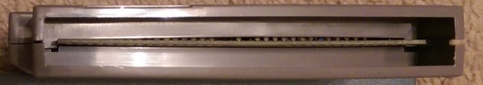
An important note before we start the next step: be sure to use flexible thin wire (28 gauge is what I prefer), and when you solder down any wires, try to keep them off the top of the EPROMs. Try to route around the sides of the chips. The chips fit very close to the cartridge case, so any too much added height on top can cause the cartridge to bulge out, like this. You might be able to get away with it if your wires are thin enough, but I try to avoid it anyway.
So, how are we supposed to rewire these boards? Let’s take a look at the Mask ROM pinout, found on the NesDev wiki, and compare it to the EPROM pinout.
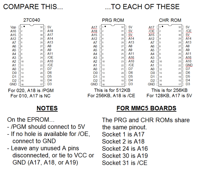
The standard EPROM pinout is shown on the left, and the socket for the PRG and CHR ROMs are shown on the right (for 32-pin boards). This will tell us how to rewire our chips. All we have to do is match the pin names together where possible. You might notice that a lot of them line up with each other, with only a few differences (the differences are underlined in red). So the easiest way to do this is to bend up any pins that are different from the socket, and add wires from those pins on each of our PRG and the CHR EPROMs to the correct socket number. Note that for these instructions, I’ll be referring to “pins” as the pins of the EPROM(s) we program, and “holes” as the pin number for PRG and CHR ROM sockets on the board.
Making a UNROM game? Read this part to get the hang of the general process, but your wiring instructions will come later.
For our MMC1 game example from earlier, since hole 24 is A16 on the PRG ROM socket, instead of putting our pin 2 of the EPROM in hole 2 on the PRG ROM, we need to bend up this pin and add a wire from it to hole 24. In general, you should bend these pins up, and clip the thin part of the pins off:
PRG EPROM: 1, 2, 24, 30, 31
CHR EPROM: 1, 2, 22, 24, 30, 31

Then, before you put your EPROMs in the slots, solder wires in the socket holes where your pins need to be rerouted. In general, you should add wires to these holes:
PRG SOCKET: 1, 2, 24
CHR SOCKET: 1, 2, 24, 31
Your first games, I’d recommend longer wires than you’d think to get the hang of it. You should eventually get a feel for how long they need to be. You can always trim them back if there’s too much slack.
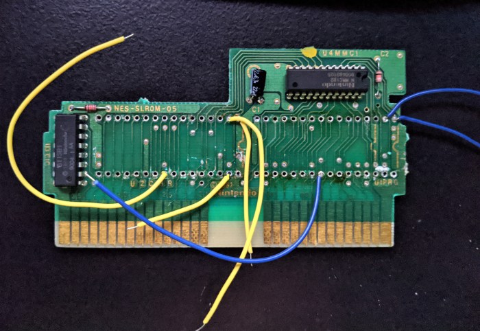
Then, place the EPROM with the bent up pins in the correct sockets, and solder those pins in on the back of the board.
Finally, solder the wires to the correct pins, and add any extra wires as necessary. Remember, try to keep the wires going around the EPROMs rather than on top. You can also loop around to the back of the board if you’re trying to access a specific hole, just be mindful that the pin numbers are gonna be mirrored if you’re looking at the back of the board! In general, route wires like this:
PRG ROM:
Wire from hole 1 to pin 30 —– (A17)
Wire from hole 2 to pin 31 —– (A18)
Wire from hole 24 to pin 2 —– (A16)
Extra wire from pin 24 to pin/hole 16 —– (/OE to GND)
Note: Pin 16 is NOT bent out of the socket.
CHR ROM:
Wire from hole 1 to pin 30 —– (A17)
Wire from hole 2 to pin 24 —– (/OE)
Wire from hole 24 to pin 2 —– (A16)
Wire from hole 31 to pin 22 —– (/CE)
Extra wire from pin 31 to pin/hole 32 —– (A18 or /PGM to 5V)
Note: Pin 32 is NOT bent out of the socket.
And there you go! You might want to tape down the wires onto the boards to keep them secure, but make sure when placing it in the cartridge you’re not pinching any wires between the case sides.
Rewiring by hand (with Flash)
As mentioned in the adapter board section, the only difference between using an EPROM and the Flash Memory is that pins 1 and 31 are swapped – pin 1 is A18 on the Flash, whereas on the EPROM it’s on pin 31. Pin 31 on the Flash is /WE, which can be tied to VCC when not programming. This is similar for the VPP pin on the EPROM on pin 1, that it can be tied to VCC when not programming the chip.
This is kind of annoying! Fortunately, this only makes a difference on the PRG ROM, not the CHR ROM (because the CHR ROM doesn’t use A18, instead the pin is tied to VCC). So, follow the instructions above detailed for the EPROM, but when wiring the PRG ROM, follow these instructions instead:
PRG ROM:
Wire from hole 1 to pin 30 —– (A17)
Wire from hole 2 to pin 1 —– (A18)
Wire from hole 24 to pin 2 —– (A16)
Extra wire from pin 31 to pin/hole 32 —– (/WE to VCC)
Extra wire from pin 24 to pin/hole 16 —– (/OE to GND)
Note: Pins 16 and 32 are NOT bent out of the socket.
Note that this is only completely true with 39SF040s. ‘020s and ‘010s don’t use pin 1 at all, as their address pins don’t go up to A18. In this case, you just need to wire pin 31 to pin/hole 32 and leave the other one alone. But it won’t hurt anything to also rewire it as if it was an ‘040.
Making a UNROM game by hand
This board is a bit different. It uses a single 128 KB ROM (PRG), but doesn’t have room for a 32-pin EPROM. There aren’t any commercially available 28-pin 128 KB EPROMs, so that means you still have to use a 32-pin EPROM instead.
Note that you can also use these steps with Flash Memory as well, as UNROM games are small enough that the differences between the Flash and EPROM don’t come into play.
Here’s some quick instructions on how to wire it up:
- Bend up pins 1, 2, 24, 31, and 32 on the EPROM.
- Place a wire in hole 22. Hole 22 corresponds to the 22nd pin of the 28-pin socket on the PCB.
- Place the EPROM in the board. Make sure that pin 3 of the EPROM is placed in hole 1 on the PCB. Pins 1, 2, 31, and 32 should overhang on the PCB. You should notice that the bent up pin 24 is on top of hole 22 with the wire coming out of it.
- Connect pins 30, 31, and 32 together, in order to power the EPROM and tie unused address pins to 5 V supply.
- Connect wire from hole 22 to pin 2, to put A16 in the right place.
- Connect pin 24 to pin 16 to enable the output of the chip, by tying /OE to GND.
Restoring save functionality to a game
If your game uses a board that can be used for games that store save data, but the original game doesn’t use that function, you might have to add some parts yourself to use the save feature. Here’s an example of a game (Spot) that uses a board that supports save games, but never used that capability itself. R1, R2, R3, D1, D2, CB, and the battery are missing.

In D1 and D2, add diodes (I recommend the 1N4148, which has low reverse leakage current). When you put them in your board, make sure you put it in correctly, because orientation matters. On most diodes, the cathode is indicated with a black bar.

The diodes prevent the NES voltage from backfeeding into the battery, since the battery operates at 3 V and the NES operates at 5 V. R2 should work fine with any value resistor around 1 kΩ, and R1 and R3 should be around 10 kΩ.
In the spot labelled “CB”, place an electrolytic capacitor (at least 10 uF, 16 V rated). Make sure the polarity is correct on this capacitor as well. This is to protect the RAM from errant voltage spikes, or fast changes in voltage level (like when you turn the game off). If you don’t want to put this in, it’ll probably still work fine, but your saves are at a (slightly) higher risk of being erased.
Now, onto the final step!
Step 6: Finalize your game
Now, you’ve got your game all wired up. Stick it back in the cartridge, careful not to pinch any errant wires, and try it out! If it doesn’t work immediately, try these steps.
Troubleshooting tips
Some games have a setting for what’s known as “mirroring”. It basically controls how graphics wrap around the screen. Horizontal mirroring is used for games that scroll vertically, and vertical mirroring is used for games that scroll horizontally.
See the little solder bead underneath the left mask ROM? It’s connecting the wire used for horizontal mirroring (denoted by the “V” on the board – yes, it is backwards). If your game is working fine, but the graphics just scroll the wrong way, or you have some other random graphical glitches, then that means you have the wrong mirroring active. Just switch to the other pad on the PCB. An easy fix, but not all games use mirroring techniques. You’ll only see these on the more basic PCB types.
If your solution isn’t that easy, don’t lose hope yet. Here are some other troubleshooting tips. This is the order I would try them in – it’s listed from shortest to longest amount of time to check.
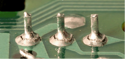
- Check for any cold solder joints. They’ll be recognizable by their “misty” or “crumbly” appearance. To fix them, just heat them up (and make sure they’re heated sufficiently) and put some new solder on them.
- Also, make sure you didn’t miss any pins or wires. You’ll have a lot to solder, after all. It only takes a single pin to be disconnected to screw up the whole thing.
- If you’re using a CIC clone chip, try pressing the reset button five to ten times, and try power cycling the console as well. This will reset the region detection on it – your chip might be set to NTSC but it needs to be PAL, for example. (Also make sure the proper capacitors are present on the board around these chips).
- Make sure your NES works with other normal games. I know this sounds silly, but you never know if your console just kicked the bucket or not between games. I once bought Super Mario RPG for the SNES and the sound didn’t work – but it wasn’t the game, it turns out my SNES audio fried since I last played!
- Check to make sure all your chips are in the correct orientation.
- Check to make sure you didn’t cut any traces on the board accidentally – if you did, you’ll have to add a replacement wire.
- If you’re using a donor, did you remember to test the original game? Maybe something else is damaged on the board, and it’s not your fault. Try replacing the capacitors (smaller ones are 0.1 uF, the large electrolytic is 22 uF). Clean the contacts that go into the NES on the cartridge. Use like rubbing alcohol or something, look online for resources, I’m not good at housekeeping stuff.
- Finally, for donors, even if you THINK everything is connected correctly, use a multimeter and check the continuity of each pin on your EPROM or other chips to its destination. This means testing the cartridge connector in some cases. This is arduous – but any time I was stumped, I usually found that just one of the pins I thought was connected wasn’t in reality. If you find one disconnected, you’ll have to add a wire to connect them.
If all else fails, you might have to desolder your chip and try a new one. Unfortunately, it’s hard to troubleshoot these boards sometimes. One thing that I’ve done in the past is put sockets on the adapter boards for the chips to sit in.

This way, I can program ROMs and try them out in a known-working board before permanently soldering them onto a real board. Plus, even with the sockets, the board still fits inside the cartridge nicely, so it’s easy to test the games out!
I also offer a socketed version of my custom boards for easy testing!
Make a label
So now you’ve got your game all made up and working, you can add the label to the cartridge. Personally, if I’m making a game that I want to look nice, I just buy a pre-made label. There are a ton of stores out there that sell them. I’m usually more preoccupied with playing the game, rather than looking at it. But if you want to make one yourself, there are plenty of resources online to help you find out how to make the labels.
Here’s a quick and dirty tutorial:
1) Remove the old label. Use Goo Gone, or I’ve heard that baking soda and vegetable oil mixed together does a decent job of removing it.
2) Find the box art, or actual cartridge label, and fit it into a cartridge template. There are plenty of templates for the label size online.
3) Print your design(s) on a full sheet label. I recommend printing more than one cartridge label at a time, because the full sheets get expensive. See if you can mooch off of someone, or buy them in single pieces from your office supply store.
4) Use a full page lamination sheet to cover your full sheet label. That’ll give it a nice shine.
5) Cut out your label and place it on your cartridge. Done!
Or, you could just keep your games looking like this. I’m not gonna judge you.
Conclusion
Congratulations! You have successfully created your own NES game!
Remember that selling reproductions of licensed games is illegal! I do not condone this! And don’t go to conventions trying to sell them, passing them off as legitimate! That’s called being a jerk. Don’t rip off genuine game collectors, we’re nice people. I can’t tell you how many times I’ve bought games on eBay or in a store that I thought was genuine, and it turned out to be a reproduction. It shouldn’t happen!
Hopefully this guide was comprehensive enough to give a good understanding of how to make a game, and why we did each step. I tried to be as clear and comprehensive as possible, but I’m sure I missed something here or there. If you find any errors, let me know and I’ll try to fix it, I plan to maintain this tutorial to keep it as accurate and helpful as possible!
Thanks for reading, and have fun!
I got a lot of information from the great people over at the NesDev forums and the endless source of NES knowledge at the wiki. They have a lot more information than I posted, and if you’re itchin’ for more technical stuff, head on over there and check it out!
And if you’d like to purchase any of my materials, head over to the store page and I’ll be happy to hook you up!

[…] This board is very simple in nature, it just replaces the rewiring instructions for NES games. Check out the main tutorial for more information about the connections. […]
LikeLike
Hello, I’d like to ask a quick question. When using an UNROM board, can I use a 128kb PRG ROM or am I limited by 64kb ROMS (due to the 28 pin situation, which on other boards seem to limit the eproms to 27c512 chips)? Thanks in advance.
LikeLike
You can indeed use larger EPROMs just fine. The bottom half of Step 5 tells you how to wire them 🙂
LikeLike
Thank you very much (I’ve read the wiring instructions, but didn’t know whether it meant that I could use bigger PRG roms or that I was constrained to using 64kb of data at most).
LikeLike
No problem!!
LikeLike
One more quick question, I have a spare w29ee011 eeprom lying around. This appears to be pretty much pin compatible with a 27c010 with the only thing being that write enable is on 5v (unrom prg). According to the datasheet WE and CE need to be low and OE needs to be high in order to actually write to the chip. can I simply substitute this chip for a 27c010? (and leave the wiring (tying 30,31, and 32 together) the same?)
LikeLike
If your programmer can program that EEPROM, then yeah you should be ok. Follow the same wiring guide as in the tutorial. The pinout seems to be all the same as a 27C010 except pin 1, which isn’t used for the EEPROM so it can be tied wherever.
LikeLike
Quick update, I’ve tried the EEPROM but it wouldn’t work (blank screen). Fortunately I used a socket, so replacing it with a 27c040 was easy.
LikeLike
Update 2, the EEPROM works fine now. It turns out that my programmer has a ‘protect’ setting for this chip, simply reburning the chip without the setting fixed it. Thanks for all the help. (Now I just need to figure out what’s wrong with my (genuine) copy of Time Lord, but that’s a different issue all together)
LikeLike
Ah sorry I didn’t get back to you sooner but glad you figured it out! Haha
LikeLike
Don’t worry , I’m happy with all the help you provided. One thing in the guide though, there’s some conflictiong information. In the wiring by hand section, you first state that pin 30 on the chr rom needs to be bent up, but a little later you say that it should not be bent out of the socket.
LikeLike
[…] How to Make an NES Reproduction Cartridge […]
LikeLike
I want to change Dr. Mario (SEROM) to RAF WORLD (SLROM)
I have cut off all the original wiring and all jumpers are finished
But I don’t know why I connected it according to the pin position of MMC1
Also followed the instructions of the article
CHR works, but PRG doesn’t work
The article says that PRG 22 24 pin is connected to #CE
But it said that it is normally connected to GND
Messed me up 😅
Is it related to the unprotected chip?
CHR&PRG: MX29F004BPC-90(EEPROM 512KB)
LikeLike
Hmm I don’t think I’m following exactly. SEROM only goes up to 32 or 64KB (512 Kbit) on the sockets. They’re only 28 pins. So you can’t make an SLROM out of it, unless your SLROM game is 512 Kbit or smaller for each chip. Most SLROM games are a lot bigger (RAF World uses 1 Mbit ROMs for both PRG and CHR). I don’t have any instructions for cutting pins on the MMC1, did I word it confusingly?
LikeLike
I noticed that Donkey Kong Jr Math, for example, has an extra binary file called title.bin. i ignored it and the title screen looks off. Is therw a way to flash that title binary on the ROM it belongs to?
LikeLike
That title file is probably the header, it’s not used by the NES but rather for emulators. The title screen is probably off for a different reason, maybe a dirty connector? I’m not sure! But the only files you need are the CHR and PRG components.
LikeLike
[…] How to Make an NES Reproduction Cartridge […]
LikeLike
[…] How to Make an NES Reproduction Cartridge […]
LikeLike