Buy the EPROM to NES Mask ROM Extended Adapter Board on my store page!
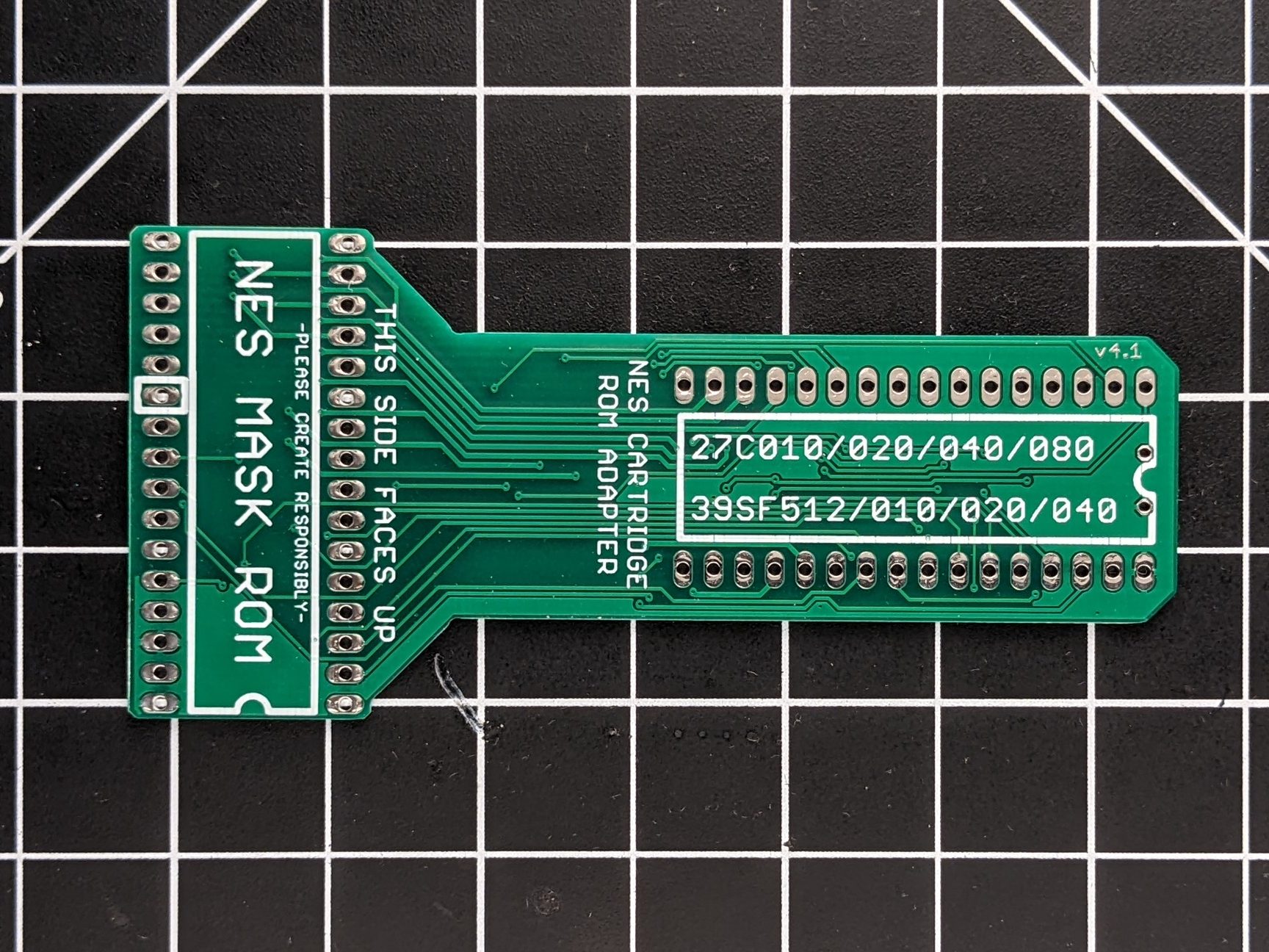
These boards house 32-pin EPROMs (27C010, 27C020, 27C040, or 27C080) and Flash (39SF010, 39SF020, and 39SF040) to fit in donor NES boards on the original Mask ROM pinout. This saves a TON of time adding wires to a donor board, and comes with the added benefit of not having to remove the original ROM.
This adapter board is made specifically for Nintendo-produced boards with 32-pin sockets, and they DO fit on UNROM boards that have 28-pin sockets as well. You might have problems getting the adapter to fit on Konami-made or other third party boards, so please check before you start. It also won’t fit on boards like NROM or CNROM, which only have 28-pin sockets. But, if you’re making a game like that, that has 28-pin sockets, you don’t need to rewire anything anyway, so you can simply just take out the existing ROM chip and place your own 28-pin part in.
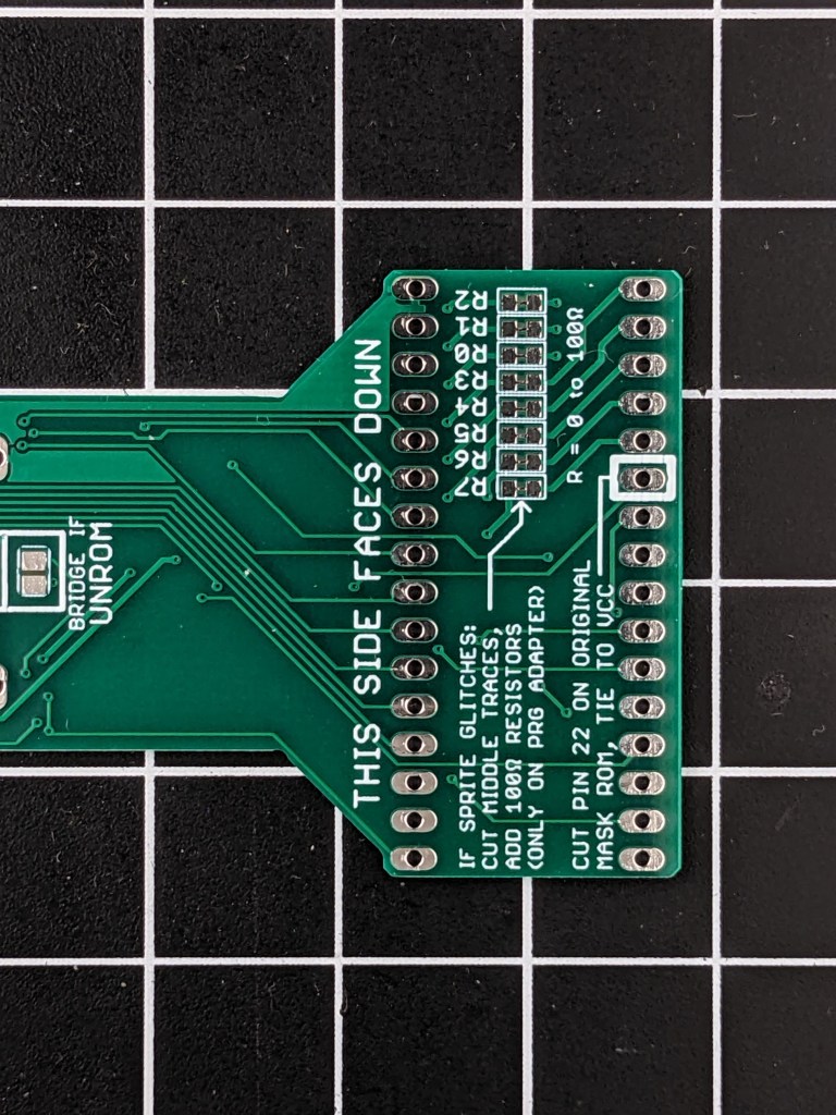
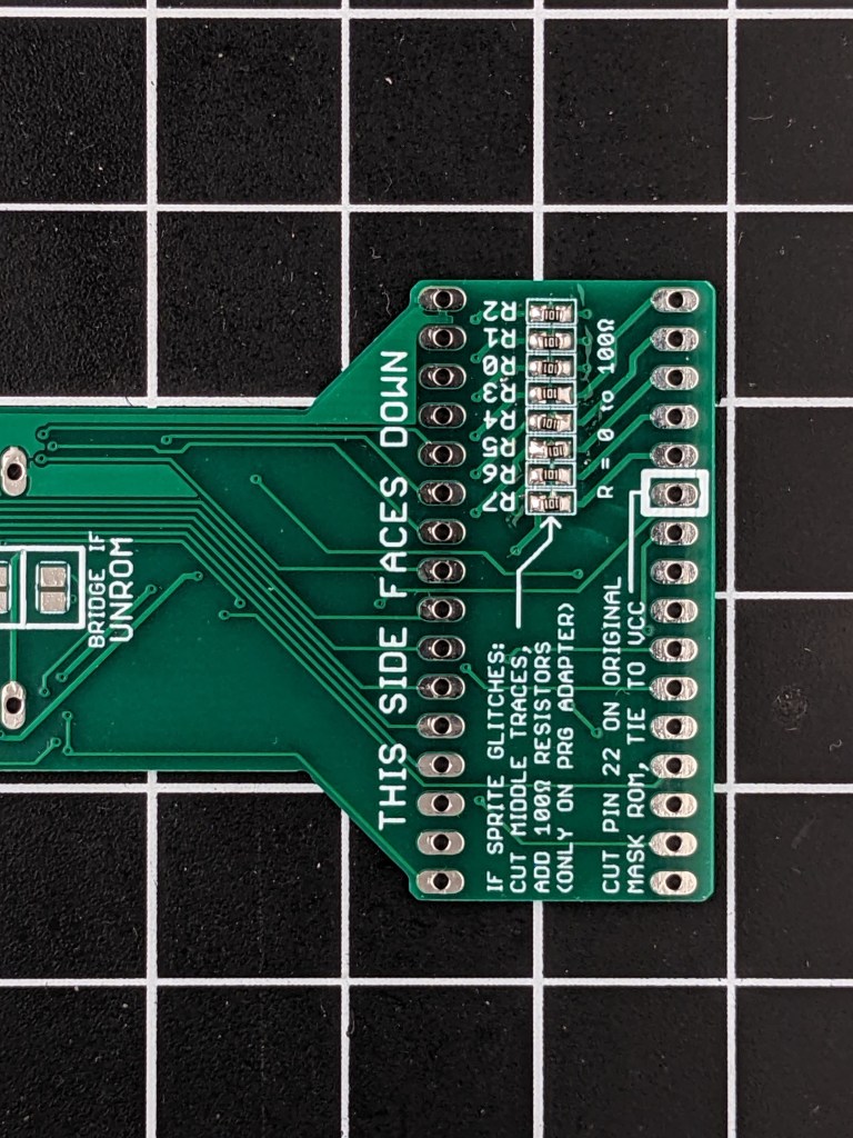
This is what the newest boards look like. The guide still applies to older revisions as well.

How to Use the Boards
Remember! You only need an adapter board for ROM chips, not for CHR RAM. So you might only need one of these boards, as all NES games will at least use PRG ROM.
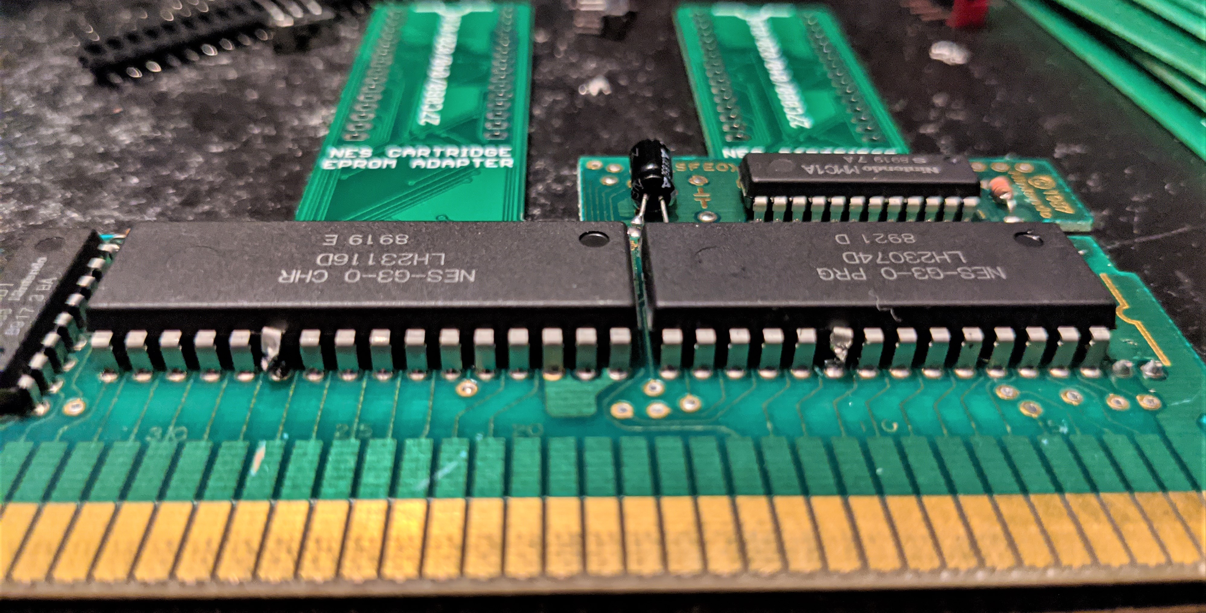
We’re going to put the adapter boards on the existing pins sticking out of the bottom of the board. We want the board to sit flat against the board as much as possible, to make sure it fits in the cartridge well, so we need to trim the pins on the other chips as close to the board as possible.

After you trim the pins, if you have them, you should be able to lay the adapters flat against the board. You might have noticed that there are some vias filled with solder. This can cause some problems if the exposed solder pads on our adapter board touch the solder on the board. It probably won’t happen, but better safe then sorry. If you’re careful you can avoid them by keeping the adapter a bit above the board, but to make it easy you can put some kapton tape down on top of the vias, creating a barrier so you don’t short circuit any pins.

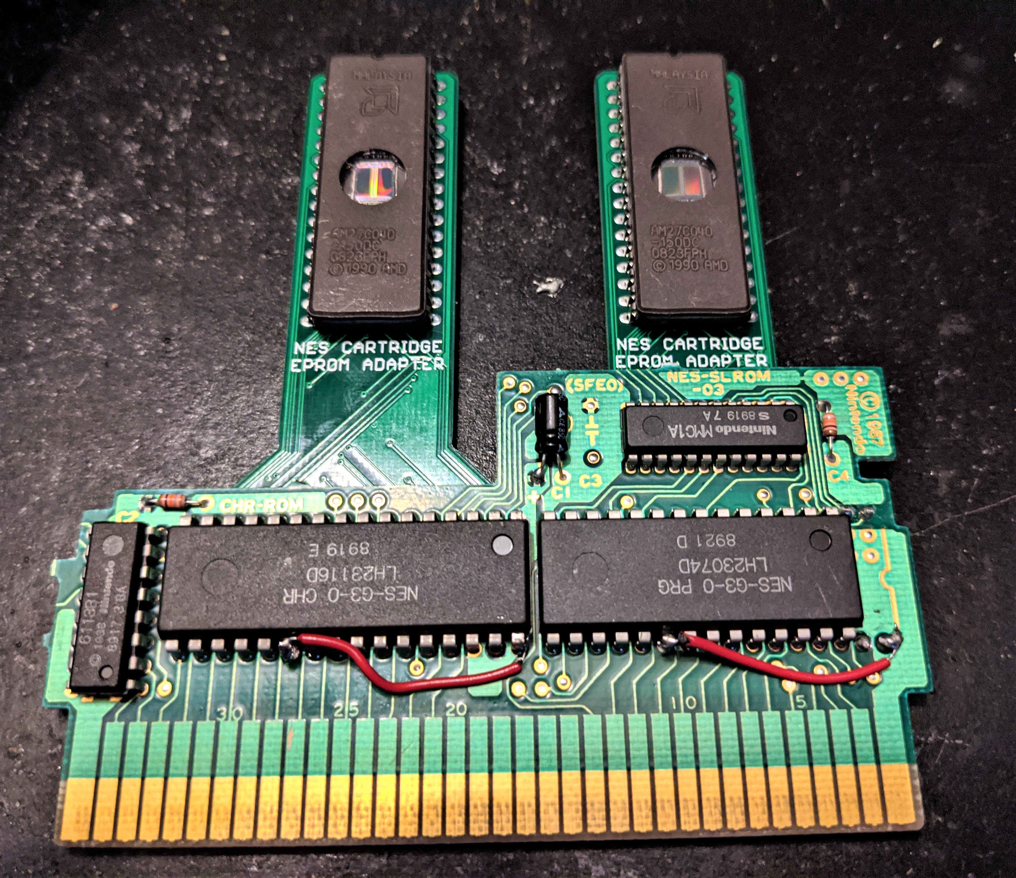
Note 1: If your board has a 32-pin socket, but only a 28-pin Mask ROM on it, you’ll have to add four wires to connect the unused donor cartridge sockets and the adapter board sockets. Just strip a wire back and heat up the existing solder, and push it through so that you can access it on the adapter board. After you’ve soldered the backside, add some solder to the topside and trim away the extra wire.

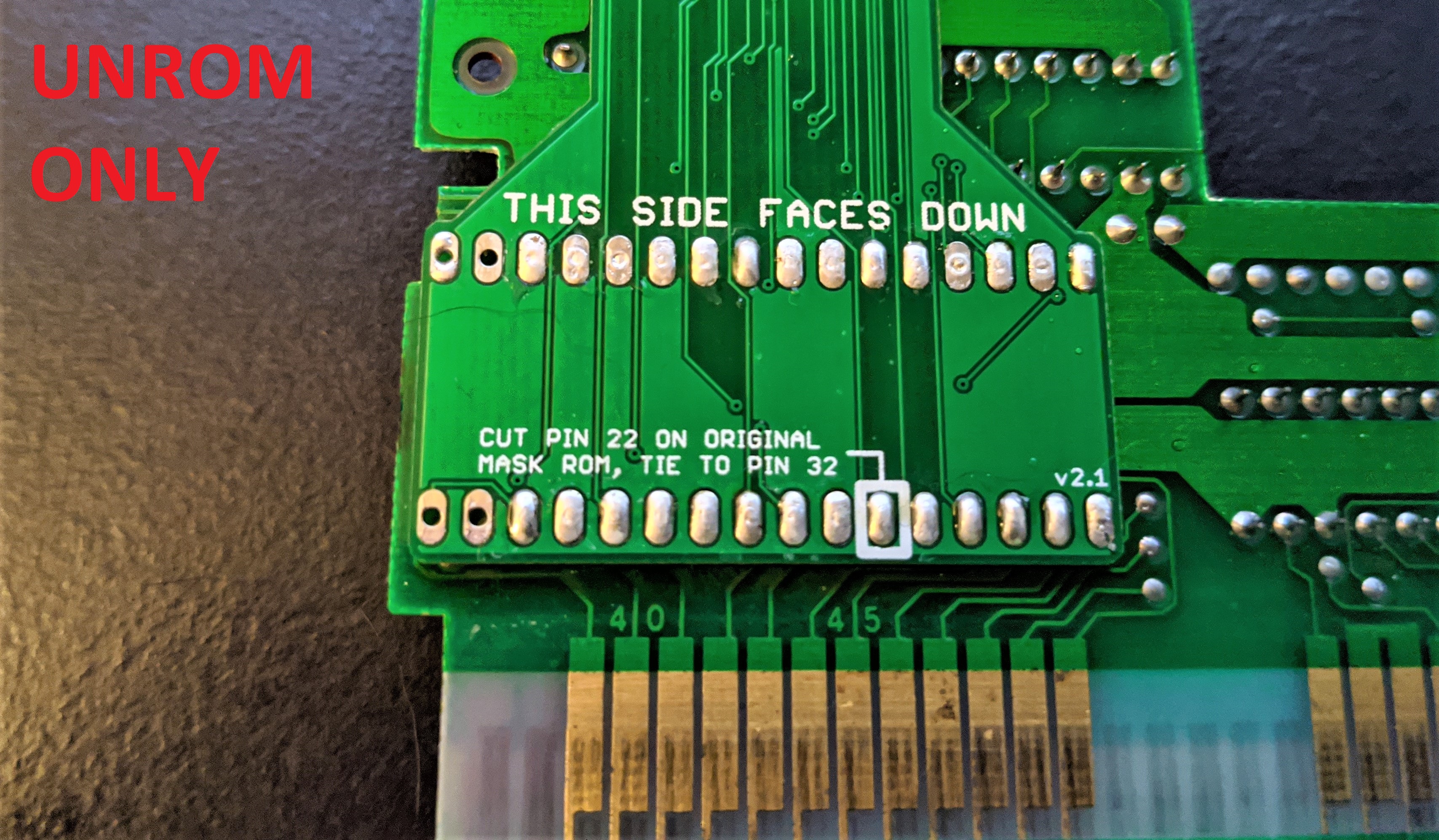
Note 2: If you’re using a UNROM board, which only has a 28-pin Mask ROM on it, you can still use the adapter. Just make sure the adapter board pin 3 sits on ROM pin 1, and adapter board pin 30 sits on ROM pin 28. Check out the picture below (view from the backside) to see which pins to leave alone. You might have to trim off some of the plastic to get the board to fit in the cartridge again, but I haven’t had too much trouble fitting it in afterwards.
Now, like the above picture suggests, you’ll want to solder the pads and make sure enough solder goes down into the hole to cover the pins, but not too much that it floods and bridges pins sandwiched between the two boards. Also, on each adapter board you’re using, be sure to solder the top set of 5 pads on the back to the correct positions depending on if it’s a PRG or CHR ROM. Just add a solder bridge between the middle pad and the left or right depending on what kind of ROM it is. Remember that flipping the board over flips the chip order too! Note that if this is for a UNROM board, you must solder the PRG side as well as bridging the two extra solder pads (remember UNROM uses CHR RAM so no adapter is needed for that).

Finally, flip the board over, and cut pin 22 on both of the original ROMs. Make sure the pin doesn’t connect to the board anymore.
Solder a wire from each pin 22, to pin 32. This will disable the original ROM by tying the /CE pin to 5V, without requiring you from taking it out of the socket.

Now we can solder our own chips into the sockets on our adapters.
This board is very simple in nature, it just replaces the rewiring instructions for NES games. Check out the main tutorial for more information about the connections.
Fixing Graphical Sprite Glitches
Sometimes, after using the adapter boards and putting your game in, you might encounter some sprite glitching. This is a somewhat rare occurrence, and usually only happens when you have things like a Famicom-NES adapter or Game Genie in your system. What sets this aside from other graphical glitches is that it affects the sprites, not the entire screen. So if you’re getting strange palettes, missing backgrounds, or weird tiles, your problem is something else, probably a bad cartridge connector or dirty cartridge edge. What you’ll see if you’re getting this kind of error, known as OAM corruption, looks something like this:
Fixing this error involves adding ~100 ohm resistors in series with the PRG D0 to D7 lines. On the adapter boards, this can be done by cutting the exposed traces with a blade and soldering resistors in place (surface mount size 0603). Be careful not to cut other parts of the board (or yourself). This only needs to be done on the PRG board!


I want to find this adapter to repro but can’t find it anywhere
LikeLike