I’m gonna try something a bit different. I’m going to just type a “stream of consciousness” here to put down some notes on this project that I want to work more on eventually. When I do get some chances to work on it, I’ll update this post accordingly with some pictures and information on how I’m doing it. We’ll see how this goes, maybe I’ll extend this to some other projects I’ve already done as well. I just want to get some more interesting content out on this website! If this is lame or weird, let me know.
So, at work, there’s an LED cube on display and it’s been there for over ten years. It’s a cube structure of 8x8x8 LEDs, and they’re tricolor! It’s got a demo that someone programmed that just goes through some nice wavy patterns, and it looks dope. But there’s not much else to it, and it’s in a nice sealed container and everything, so getting to it isn’t the easiest to do. Plus, if anyone were to go tamper with it and break it, they’d probably be vilified for years to come. I don’t think anyone has the source code for the thing anymore.
So naturally, since I can’t play with it myself, I want to make one of my own! The problem is, making an LED cube like that is tedious, to say the least. The logic behind it, maybe not so much, but actually constructing it looks like it’s a pain – especially because it’s 512 LEDs in total, with four legs to solder to. Here’s what the one at work looks like – it’s crazy precise and really neatly laid out!

I think to start out, I want to just make a 4x4x4 to get the concept down, and because getting 64 LEDs is cheaper than 512. Once I have a working small model, it should be pretty easy to scale it up.
In an LED cube, you don’t drive each LED individually and you don’t drive them all at the same time. That’d be a lot of wiring and a lot of continuous power and a lot of work! Instead, you cycle through the LEDs in groups, layer by layer, very quickly. If you pulse them fast enough, the human eye can’t detect the distinct periods of the LED being off, so it looks like you’ve got the whole thing lit up at once. If the on-time isn’t long enough, I’m thinking about adding some extra capacitance to keep the LED lit longer. But we’ll see when I try it out for the first time.
Anyway, here’s the circuit I had in mind. Sorry for the crude sketch. I’ll try to explain my logic.
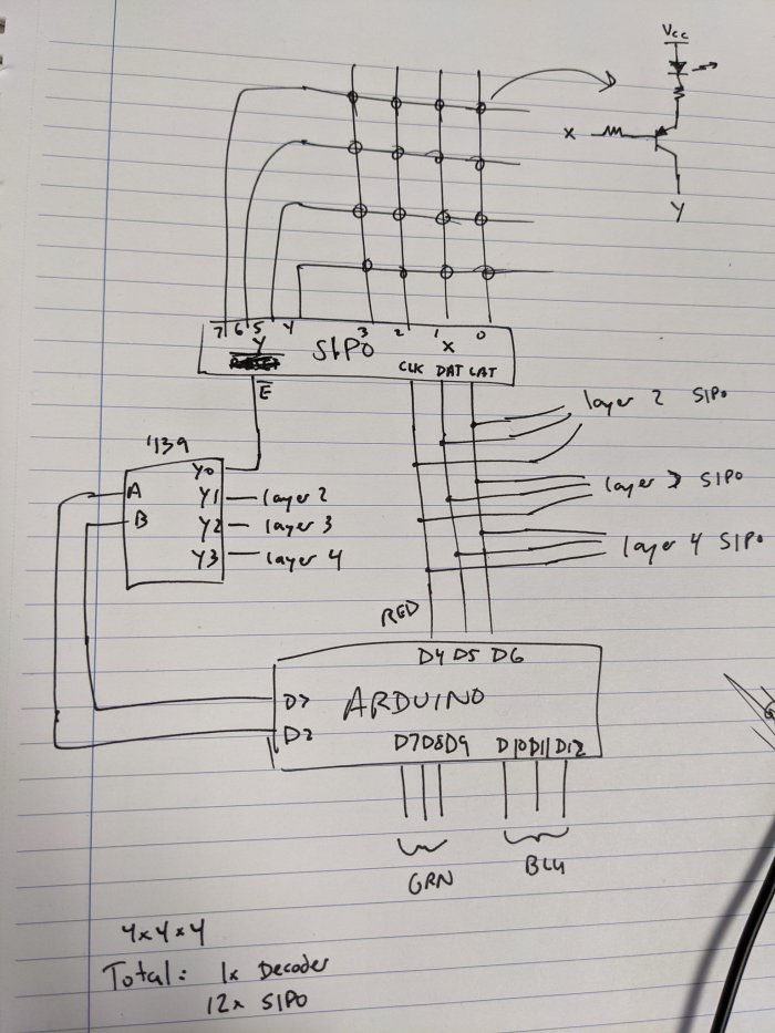
Ok, let’s view this from the standpoint of just one color for now. So all the logic will be driven by an Arduino. D2 and D3 will drive a ‘139 decoder. The decoder pulls each of its output pins low when that pin is selected, and keeps the others high. D4 through D6 will drive inputs to a SIPO (serial in, parallel out) shift register. The shift register will control the transistor drivers for the LEDs. The Arduino sends serial data and loads it into the SIPO by using the clock, then when the latch pin is activated the output on the parallel pins is made.
Also note the output enable pin /E on the shift register being controlled by the decoder. Basically, each layer will have one SIPO shift register, and which layer is selected to light up will be cycled through from the decoder. So basically, the SIPO lights up each row/column on one layer, the decoder shifts to the next value, and the SIPO lights up that one, and so on until it repeats.
On this 4x4x4, I can use just one SIPO for the entire layer – if I was going to 8, then I’d need two SIPOs, one for the X axis and one for the Y. You can see that I designated D0 through D3 as the X axis, and D4 through D7 as the Y.
Each of the circles in the grid above indicates where an LED driver will be located. The LED driver is simple – the input to the base of the NPN transistor is the X value, and the emitter is the Y value. When X is high, and Y is low, current flows into the base of the transistor and turns it on. This allows current to flow through the LED. If X is low, or if Y is high, then the transistor doesn’t turn on and the LED stays off. The logic will be such that the entire X values are loaded in, and the Y values are cycled one by one, for a total of four writes to the SIPO.
Let’s say I wanted to make the layer light up like this:

First off, apologies for such a bad drawing. I’m writing this on my couch right now with a crappy laptop and no mouse.
Anyway, the datastream for the SIPO would look like this (D7 as most significant bit, D0 as least significant bit)
1110 0001
1101 0010
1011 0101
0111 1010
See how the zero in the “Y axis” nibble of the byte controls which row is active? So basically, I’m going to cycle through these four instructions as fast as possible, and if I repeated it continuously, you shouldn’t be able to tell that I’m only lighting up one row at a time.
Now, instead of just cycling through this layer over and over again, the next step is to change the ‘139 selection from 00 to 01 to shift to the second layer. This layer would then run through the same row-by-row lighting routine as I just described. And, naturally, once it finishes the top layer, it cycles back to the bottom. So, one decoder and four SIPOs can control the entire collection of 64 LEDs. Since only one SIPO is activated at one time, we can just tie the data, clock, and latch pins all together to control them from one Arduino output pin each.
Ok, so great! We’ve got the routine for lighting up the whole cube! But wait… that’s only for one color. Since this is an RGB LED, we have to do the same thing for the other two colors. No problem, just repeat the process for each color. We can do all three colors in parallel, by loading each layer’s information at the same time for each color. Then, conveniently tying all the enable pins of each color’s SIPO together and attached to the ‘139 decoder. So we still only need one decoder for the entire cube to cycle the layers. And again, since we’re clocking in and commanding the output of the SIPO to be simultaneous for the entire layer no matter the color, we can attach all the clock and latch pins together. We just need an extra data pin for the other two colors. I know the schematic up there says otherwise, that was a mistake.
When all is said and done, that’s three SIPOs per layer (one for each color), four layers of SIPOs, for a total of 12 SIPOs. D2 and D3 control the layer selection through the ‘139 decoder. D4 and D5 control the clock and latch pins of the SIPOs. D6, D7, and D8 will be the data lines for each color. (Again, I know the schematic is different, sorry but I’m too lazy to draw a new one right now).
Also, I think it’d be beneficial to get little PCBs made up for the LED drivers. Maybe one for each LED, with connections available to daisy chain them all together. Since they’re all the same circuit, it could be nice to have a compact way of hooking it all together and make it cleaner. Plus, it would make expanding to the 8x8x8 easy.
Now, writing the code for all that will be the bigger challenge. In the end it’s just getting the logic right, and the nested for loops. Nothing too crazy complicated. But making cool patterns is gonna take some trial and error. I need to write some nice streamlined and easily editable code to make it easier to make new light shows! There’s also the concern of how fast the Arduino can load in the data to the shift register, and if the cycling through the layers will be noticeable. But again, I can always add capacitors to keep the LEDs on longer. Just can’t pick too big of a time constant!
I have no idea when I’ll get around to actually doing this, but it’s been on my mind a lot lately, so I wanted to write it all down to save my thoughts and not have to figure out a wiring scheme again.
Let me know what you think of it!
