Note: This is an ADVANCED installation. It is quite tricky to get the board and chip to fit in the cartridge. Try to keep the board and chip as CLOSE to the PCB as possible. Before permanently soldering in the board/chip, it might be helpful to hold it in place with tape or only one solder joint so you can easily reverse it if necessary.
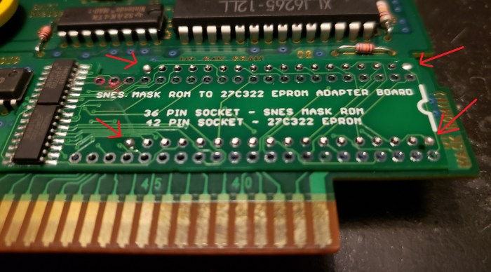
This little board adapts the 32 Mbit 27C322 EPROM to fit in donor SNES boards or custom SNES PCBs. This saves a TON of time adding wires to your board. All you need is two rows of 18-pin headers. A protoboard or perforation board is also very handy, but you don’t absolutely need it.

I also made a board similar to this one for 27C160s instead. They’re a bit easier to manage, since you don’t need multiplexers. You can follow the same methods here to mount the 27C160 board properly, but all the pictures will be using the 27C322 adapter.

Let me start off by saying these boards are extremely thin and therefore extremely easy to break! Be careful not to flex this board too much!
How to Use the Board – Method #1
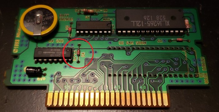
The first thing you’ll need to do is move any parts to the left of the EPROM socket to the back of the board, if they interfere with the adapter. Just heat up the solder and pull the part out (probably a capacitor) and solder it to the backside instead.
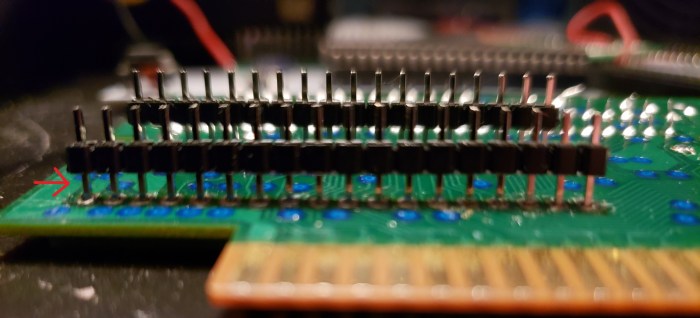
After that, get two sets of 18-pin headers. Insert them in the socket, and place the adapter board on top. Make sure the pins only poke through the top a little bit, just enough to get a good amount of solder in the pads. I usually tack each corner first, then fill in the middle pins. Make sure you put enough solder on these pins, especially the bottom row of headers, because it will be hard to access them after the EPROM is in the board.
The bottom of your board should look like this below. Clip off the black plastic part, and solder the remaining pins to the bottom of the board. Be sure not to heat these pins up too much, or they may fall out of the socket! The heat can reflow the solder on the top connections you just made.
Once you’ve soldered the bottom of the board, inspect the top to make sure you didn’t accidentally reflow solder down from the top of the adapter board. Make sure every connection is good before continuing.
Before messing with the EPROM, I would try using your programmed EPROM in a prototype board with a socket or have some other means of checking to see if the game works on the SNES before you solder it in place. Once it’s in there… it’s not gonna come out easily or cleanly. So please, make sure your EPROM is programmed correctly before continuing!!
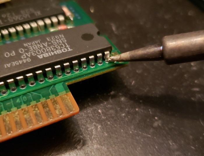
Now, take your EPROM (programmed!) and cut off the pins so that only the wider part is left.
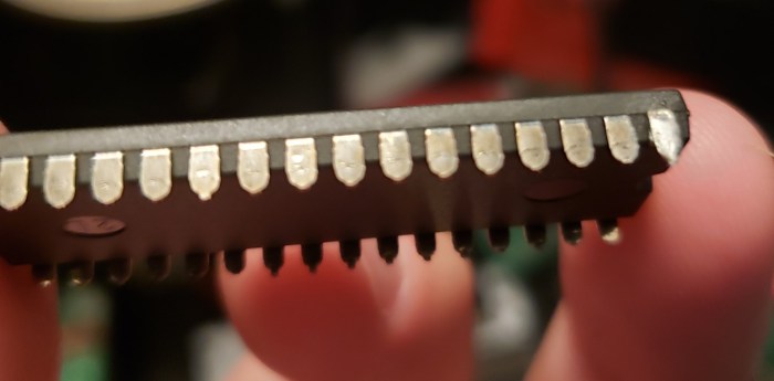
Now, place your 27C322 EPROM in the 42-pin socket and try to get it to lay as flat as possible. You should probably try putting the board back in the plastic case just to make sure it’s as low as possible. If there’s any interference, you can try cutting the pins farther down, even taking out part of the wider part of the pins, or your header pins you soldered at the beginning might be too tall and you’ll have to cut them down. Once it can fit ok, solder the pins to the socket on the outside of the package like this.
Now, just tape up the window on top of the EPROM and you should be good to go!

How to Use the Board – Method #2
Like Method #1, the first thing you’ll need to do is move any parts to the left of the EPROM socket to the back of the board, if the adapter interferes with them. Just heat up the solder and pull the part out (probably a capacitor) and solder it to the backside instead.
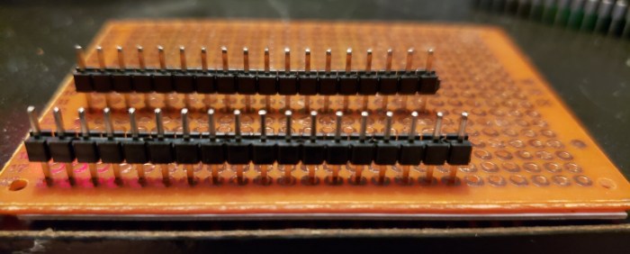
Now you’ll want to do is get your headers ready. I do this first because if I have problems, this is the step I’ll have problems on. Place your two rows of 18 pins in the protoboard with 5 rows between them. Don’t push them in all the way. Then, place the adapter board on top of these two rows of pins, so that the pins barely stick out of the 36 pin socket on the adapter board. Make sure the black plastic is on the opposite side of the protoboard.
(If you don’t have protoboard, just put the pins into the board like the second picture below so that they barely stick out. You should probably have a guide to line the pins up correctly, like the SNES PCB, so you don’t solder them in crooked.)

(Note that these pictures are from a white prototype board I made. If you have 27C322 adapter boards, you’ll already have the multiplexers soldered onto the board.)
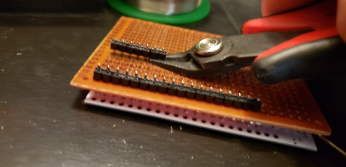
Now, carefully solder the pins in on the top of the adapter board. You want good connection with the solder, but you don’t want too much of the pin sticking out of the top. Now, gently push down on the protoboard so that it pushes against the black plastic on the rows of pins.

Sometimes you can get the black plastic off the pins completely this way, but I’ve found it’s good enough to just wiggle it a bit and cut off the black plastic with clippers. If you don’t have the protoboard, just clip the pins as close to the black plastic that you can get.
Now, you should have the adapter board with 36 pins in it. You should place it into your donor cartridge just to make sure it fits ok. You might have to move a capacitor or something else where the left part of the board meets your donor cartridge. In this picture, you can see I had to take a capacitor out of the board and resolder it on the bottom of the board.

Before messing with the EPROM, I would try using your programmed EPROM in a prototype board with a socket or have some other means of checking to see if the game works on the SNES before you solder it in place. Once it’s in there… it’s not gonna come out easily or cleanly. So please, make sure your EPROM is programmed correctly before continuing!!
Now, put your 27C322 into the adapter board and see how low you can get the EPROM to the surface of the board. If it doesn’t go down all the way, take it off and try carefully trimming the header pins sticking out of the board that are underneath the EPROM. Just be really sure the EPROM is in as far as it can go. This is important to get right, because if you don’t, your board won’t fit back into the cartridge. Once it’s set, solder the pins.

See how the solder kind of blobs up on the pins of the EPROM? You want to make sure you have good connection from the EPROM to the board because we’ll be trimming those pins on the bottom. But make sure you don’t accidentally solder two pins together! Now, flip the board over, and cut down the 42 pins on the 27C322 as close as you can get to the board. Be sure to leave the header pins exactly how they are!

You’re nearly done! Put your board into the SNES socket, and solder the header pins into the cartridge PCB. Be careful to not heat up the pins too much, as they may cause them to come loose from the adapter board! Spend as little time as you can soldering these pins to the board without making a cold solder joint!!
Your final product should look and work great!
How the Adapter Works
If you look at the pinout of the 27C322, you’ll notice the data pins go from Q0 to Q15. That’s because this is a 16-bit EPROM, where each word is 16 bits instead of the 8 bits the SNES uses. So the first address of the 322 contains the first TWO addresses the SNES will use, the first from Q0 to Q7 and the second from Q8 to Q15.
Let’s look at the TL866 programming window to see what I’m talking about. Compare the left window here, which is an 8-bit EPROM, with the 16-bit EPROM on the right. These numbers are in hexadecimal, or four binary bits. So you’ll see on the 8-bit bus two-digit hex numbers, while on the 16-bit bus you’ll see four-digit hex numbers.
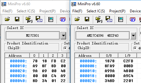
Let’s use the first two addresses, which are 0x78 and 0x18, as an example. If on a 16-bit EPROM we read only D0 to D7 (0x78), we’re completely missing all the data on D8 to D15 (0x18) – with each increasing address request from the SNES, we’re skipping every other 8 bits segment. In effect, on a 16-bit EPROM, A0 from the SNES should point to the bottom half (A0 = 0) or top half (A0 = 1) of each word. And therefore, A1 from the SNES is acting like the 27C322’s A0 pin. So all we have to do is shift the address pins from the SNES one position – A1 on the SNES is connected to A0 on the 322, A2 on the SNES is connected to A1 on the 322, etc. Then, we use the A0 pin from the SNES to control which half of the 16-bit word we read from. We can do this using a multiplexer.
A multiplexer is a device that is essentially a digitally controlled selector switch. In our case, we need eight separate switches to change between two different data lines all at the same time. D0 on the SNES should either read D0 or D8 from the 322 EPROM, D1 on the SNES should either read D1 or D9 from the 322 EPROM, and so on. When A0 from the SNES is 0, the multiplexer will route D0 to D7 from the 322 to the SNES, and when A0 from the SNES is 1, the multiplexer will route D8 to D15 from the 322 to the SNES. Make sense?

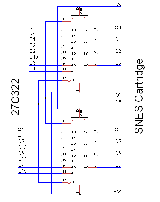
The 74HCT257 is a quad-package two-line multiplexer. If we use two of them in parallel, we can control all eight data lines. So, here’s how the EPROM connects to the multiplexers and the SNES Mask ROM pinout.

Finally, here’s the resulting schematic of the multiplexers. The rest of the pins on the EPROM go to the matching cartridge connector pin, but offset by one (A0 of the EPROM goes to A1 of the SNES cartridge connector, etc).

[…] 27C322 to SNES Mask ROM Adapter Board […]
LikeLike
Thanks for this. I really should look into this, my NFL donor cart is lying around for a year now if not longer.
LikeLike
Hi, just wondering about the case when the SNES takes /CE High – what will happen to the outputs of the multiplexers?
If there is a case when /OE is low and /CE is high (not sure this occurs, maybe you can correct me on this) then obviously the SNES is not expecting output from the ROM since normally the high /CE would send the data lines from the ROM to a High-Z state. However, in this arrangement you will have an unpredictable output from the muxes since they will be outputting something (because /OE is low) but the data inputs from the ROM are High-Z meaning the data outputs from the muxes can be high or low, but they definitely won’t be High-Z since this state does not propagate through the mux…. Won’t this cause bus conflicts?
LikeLike
Hey, sorry this took so long to get back to you on. Luckily the answer is easy!
The /CE pin will never be high when /OE is low. Flipping them would indeed cause bus conflicts – as I have found out personally from a miswiring on one of my boards.
LikeLike
Nice one, thanks for the reply!
LikeLike
[…] 27C322, 27C160 to SNES Mask ROM Adapter Board […]
LikeLike
Would there be any issue using two 27c160 adapter boards on a two rom board? Other than making it fit.
LikeLike
As long as the sockets are 36 pin, it should work ok
LikeLike
Thanks for the fast response! Also, any chance the 27c322 slim boards will get restocked soon? Great work and designs btw.
LikeLike
Thanks 🙂
The slim 322 boards have been out of stock for a while now, because the place I order boards from haven’t had the particular chips in stock.
Though, maybe I could order the boards without chips on them for those with the ability to solder them on. I’ll look into that 🙂
LikeLike
NO ENVIA A MEXICO placas para la 27c322, me interesa
LikeLike
Could you please tell me where I can obtain the Gerver file for the 27c322 slim?
It’s not on Github
LikeLike