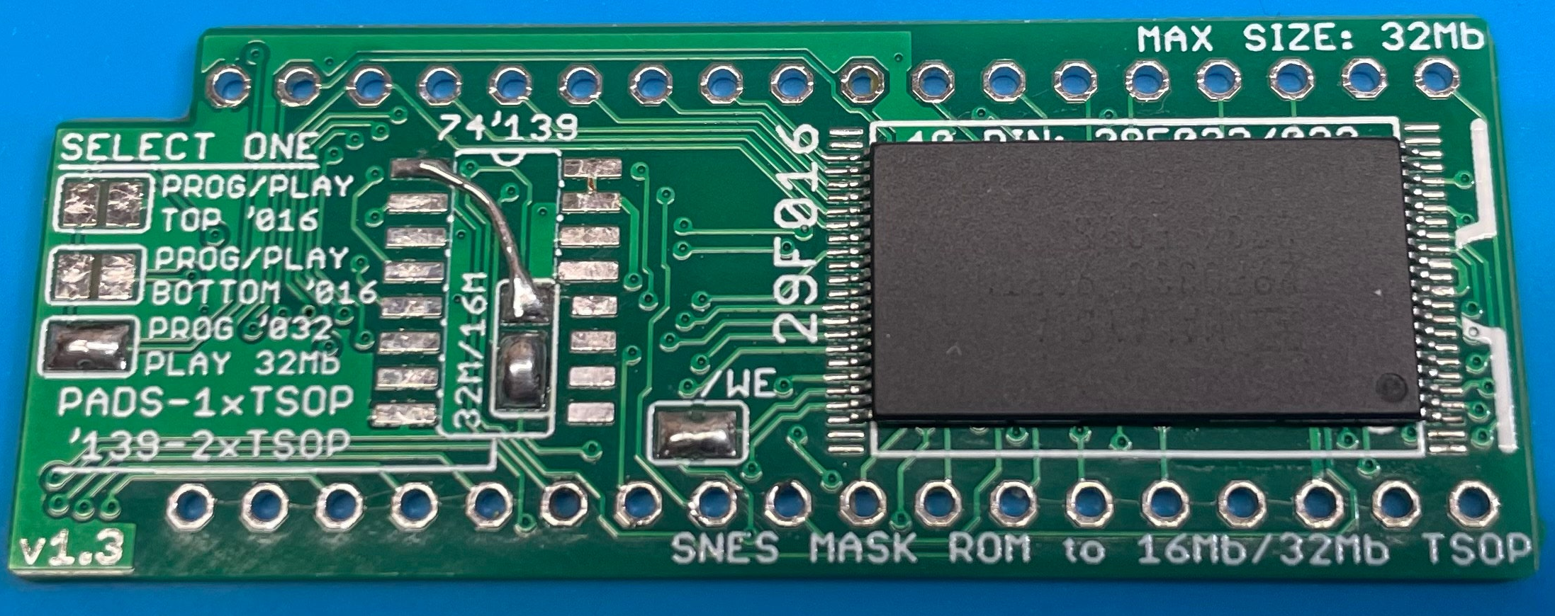
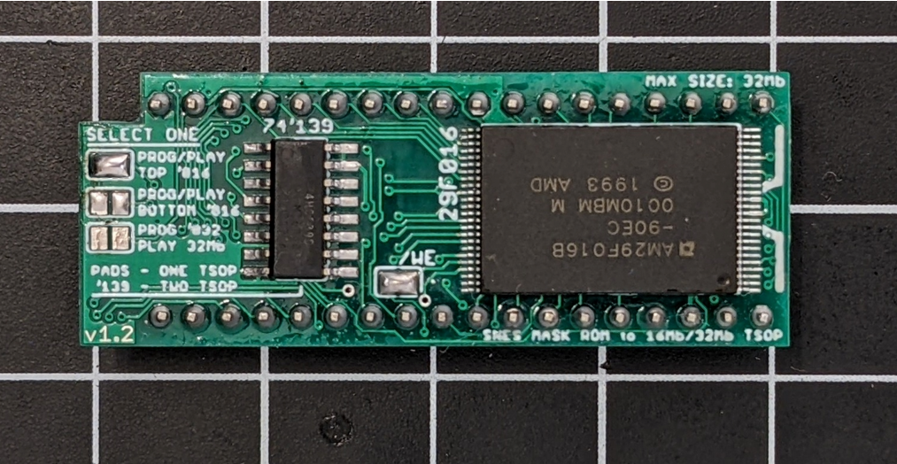
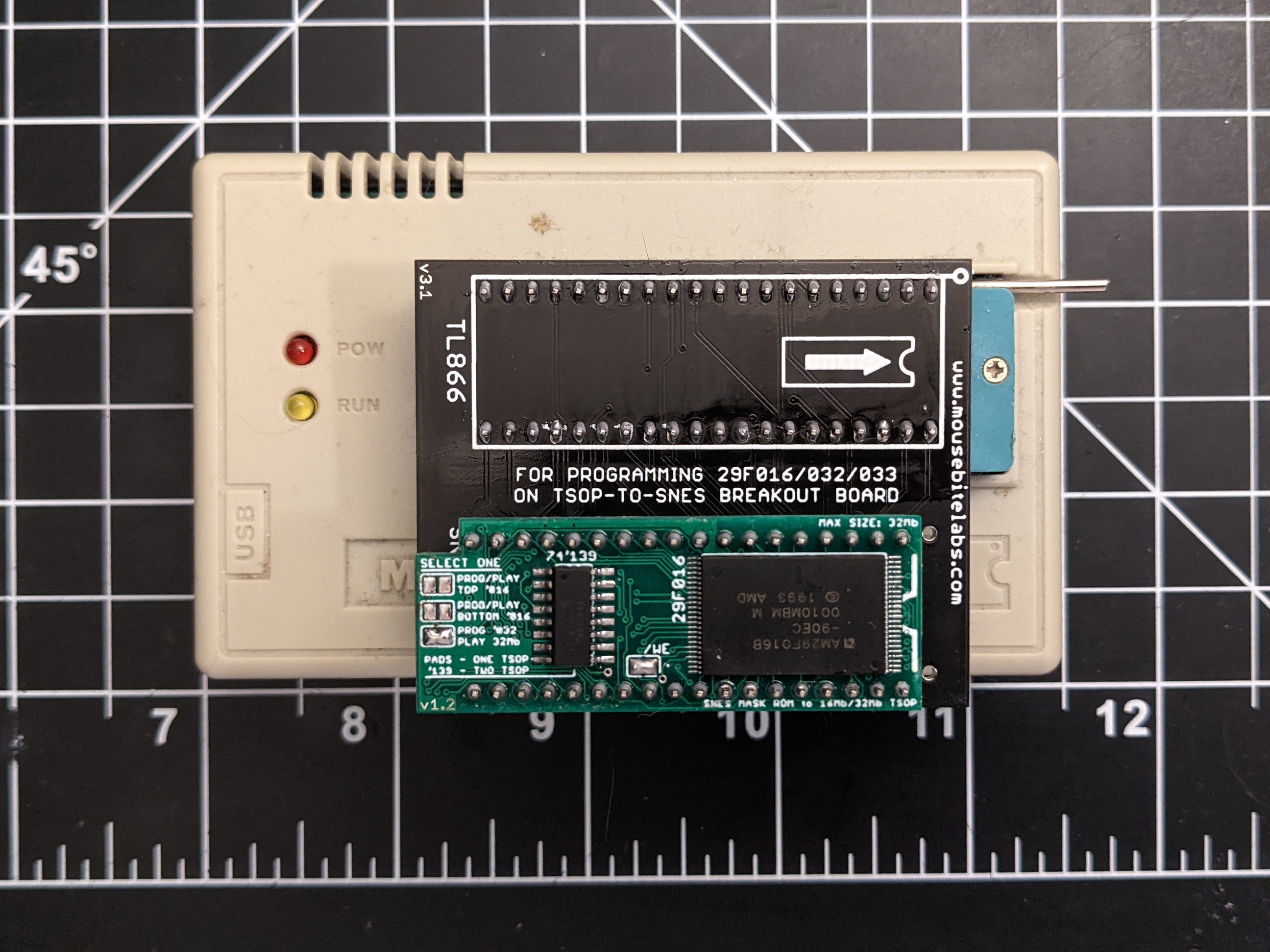
This board lets you use 29F016 or 29F032/033 TSOP EEPROMs for making SNES games! This is the first board that I’ve seen that allows you to combine two 016’s on one board to program a full 32 Mbit SNES game. You just need a 74’139 decoder if you want to use two EEPROMs, otherwise you can just use a single EEPROM on the top of the board.
You can program the chips on this board with the TL866 and my TSOP-to-SNES programming adapter.
Note that I would only recommend using this board if you’re very proficient at surface mount soldering. You can get solder practice kits to learn how to drag solder, which is the method I recommend. Watch some videos on how to do it if you aren’t experienced, and practice on less expensive parts first. If you’re not experienced I’d recommend using other through-hole options.
Check out the main tutorial for how to prepare the ROM file.
Adding Parts to the Board
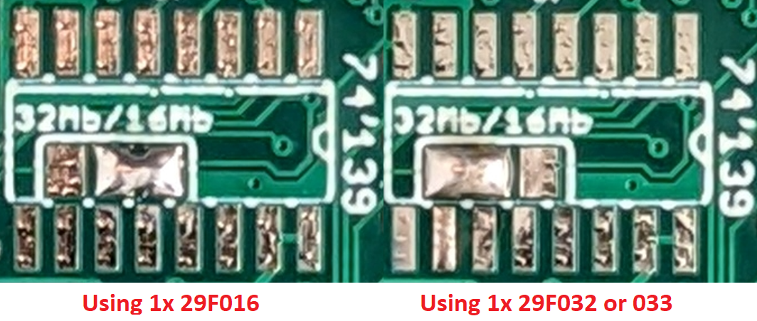
There are three configurations for this board – 16 Mbit with one 29F016, 32 Mbit with two 29F016s, or 32 Mbit with one 29F032 or 29F033. The first step is to solder the TSOP chip(s) onto the board. If you’re going to use a 29F032/033, you should solder it on the top set of pads in the 40-pin rectangle indicated on the board. And if you’re using two 29F016 chips, you need to add a 74’139 decoder (do not solder the pads underneath the chip).
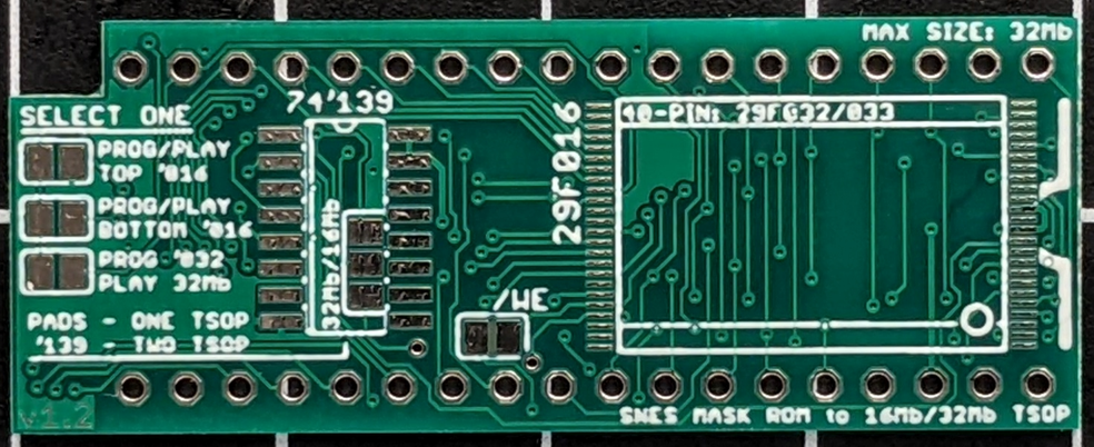
The back of the board has a spot for a second 29F016, if you’re making a 32 Mbit game with two 29F016s.
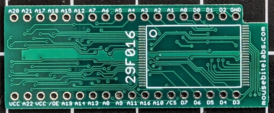
After this, you can solder two rows of 18-pin headers, so you can program the chips and place them on the board.
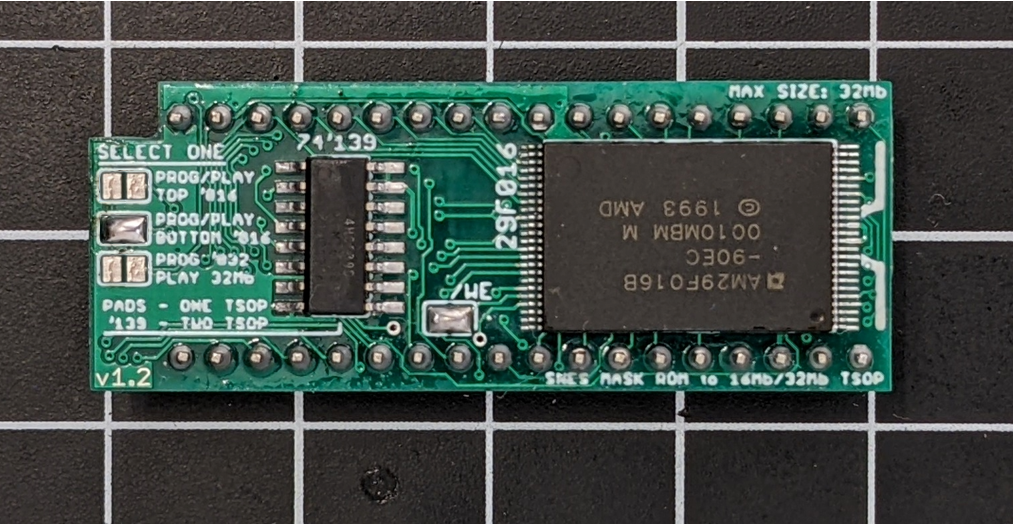
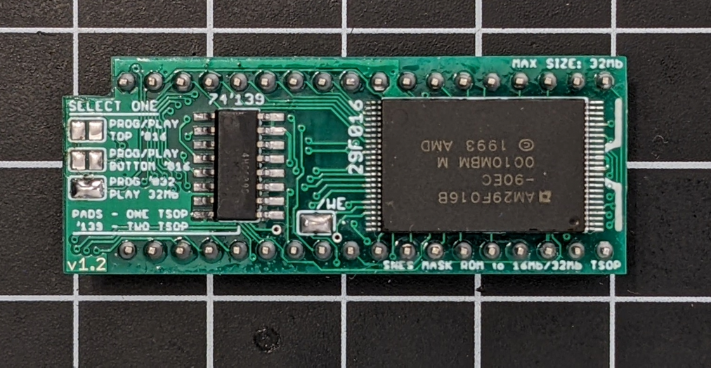
Configuring the Solder Pads
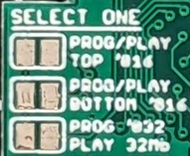
There are five sets of solder pads on the board that configure the board for program and eventual use.
- The first set to take care of, only if you’re not using a 74’139 decoder, is the set labelled 32M/16M. If you’re using a single 29F016 or using a 29F032/033 to make a 16 Mbit game, solder the pad from the middle to the top for 16 Mbit mode. If you’re using a 29F032/033 for a 32 Mbit game, solder the middle pad to the bottom for 32 Mbit mode. Again, only solder these pads if you aren’t using a 74’139.
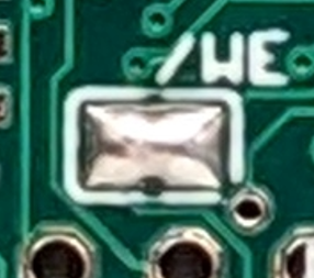
- The other set of solder pads that are quick to take care of are the /WE pads. The right-most solder pad is directly connected to the /WE pins on the two TSOP sockets. The left solder pad connects to pin 36 on the SNES ROM pinout, which is normally tied to VCC when in a cartridge PCB. These pads should be bridged by default; I included them for Sanni support (which is untested until I get a Sanni to test these with).
- The final pads to take care of are on the right. Only one set of these should be bridged at any time. Here are the functions:
-
- The top set (PROG/PLAY TOP ‘016) should be bridged if you are programming the top 29F016. This will hold the first half of a 32 Mbit game, or one entire 16 Mbit game. If you’re only using the top 29F016 to make a game, keep it bridged all the time; if you’re making a 32 Mbit game, desolder the bridge after you program the top half.
- The middle set (PROG/PLAY BOTTOM ‘016) should be bridged if you are programming the bottom 29F016. This will hold the second half of a 32 Mbit game. When you’re done programming, desolder the bridge. (If you want to make a 16 Mbit game on one 29F016 TSOP, then you can use the bottom TSOP instead of the top, just keep the pads bridged for playing the game)
- The bottom set (PROG ‘032/PLAY 32Mb) should be bridged if you are using a 29F032/033, or if you’ve finished programming both the top and bottom 29F016 for a 32 Mbit game. These pads need to be soldered to play a 32 Mbit game.
4. If you are making a game with a single 32 Mbit EEPROM, you must also add a bodge wire from the top pad in the middle of the 74’139 footprint to pin 1 of the footprint.
Example for Making 32 Mbit Games with Two 29F016s
For this example, I’ll make a 32 Mbit game with two 29F016s.
1) First is to solder all the parts on the board. I solder the two 29F016 chips, along with the 74HC139. I also add the header pins in last. Since I’ll be programming the first half first, I bridge the top set of pads on the left. Also bridge the /WE pins.
2) Next is to program the top 29F016. I already prepared the ROM, and split it into two 16 Mbit halves. Just need to use the TL866 to program the first half of the game.
After it verifies, I desolder the top pads on the left and bridge the middle pads to access the bottom 29F016.
3) After the second half programs, I desolder the middle pads and put it into “play 32Mb” mode by bridging the bottom pads.
4) Take the board out of the programmer, and solder it into the cart PCB. All done!
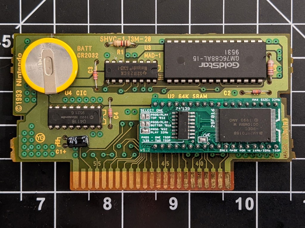

[…] pretty expensive, so a cheaper option is to solder the TSOPs to the TSOP-to-SNES breakout board, like mine, and make an adapter to program the chips mounted on the breakout […]
LikeLike