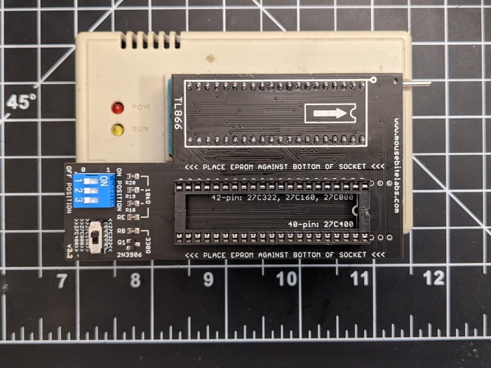
Buy the 27C322, 27C160, 27C800, 27C400 Programming Adapter from my store!
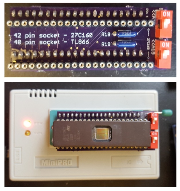
This adapter allows you to program the 27C322, 27C160, 27C800, and 27C400 chips on your TL866 programmer. The board has gone through a lot of revisions, but here’s the current model. It even has space for a ZIF socket!
The 27C322 and 27C160 EPROMs are 42 pins wide. The TL866 and TL866II programmer only has room for 40 pins. So how are we going to deal with that? Well, the short answer is, we’re going to trick the TL866 into thinking we’re programming a different EPROM. The EPROM we’re going to tell it to program is only 4 Mbits large. Using this EPROM normally would only utilize address pins A0 through A17. The 27C322 goes up to A20, and the 160 goes up to A19. By manually controlling A18, A19, and A20 (for the 322), we can program our ROM in 4 Mbit chunks to fill up the memory space.
Assembly
View the instructions at my github page: https://github.com/MouseBiteLabs/27C322-TL866-Adapter
Splitting the ROM
If you’re following the SNES tutorial, you might already know how to do this part. If not, you can check out Step 6 of the tutorial here.
If you don’t want to use SNES ROM Utility, or are using this programmer for something other than SNES games (like, for Genesis games), you can use this utility to split the files instead. Note that it WON’T remove any header information for SNES games! But otherwise, it’s very simple to use; just load up the ROM, pick your destination folder, and type in a custom size of 512 Kbytes (which is 4 Mbits).
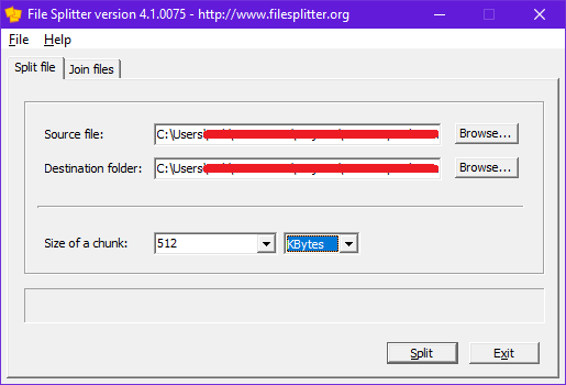
Now, you’ve got your 4 Mbit chunks to program with the TL866. These chunks will end in a .chunk001, .chunk002, etc. file extension after splitting. You can still load these files up into the programmer without any issue – no need to change the file extension back.
How to Use the Programming Adapter
Load up the 27C4096 chip on the TL866 software, and load up the first chunk from your original ROM. Change the VPP to 12.5 V, as this is dictated for programming voltage in the datasheet. Then, uncheck the “Check ID” option. Note that if you have the new TL866II and are using “Xgpro” software, you need to uncheck “Pin Detect” as well. Your window should look like this:

Here’s a table of how data is programmed into the EPROM. If A18, A19, or A20 is a “0”, that means tie it to GND, or if you’re using the adapter, put the switch in the “OFF” position. If it’s a “1”, that means tie it to VCC, or if you’re using the adapter, put the switch in the “ON” position. Program the 4 Mbit chunks in sequential order in the banks.
For the 27C322, use these switch positions:

For the 27C160, use these switch positions:
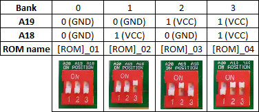
For the 27C800, use these switch positions:
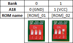
For the 27C400, keep all switch positions OFF. Also, because the 27C400 is only 40 pins, and not 42 pins, make sure to put the EPROM with pins 1 and 42 exposed.
If you get an error while programming with the MiniPro – make sure your chips are in the correct orientation, each bank is blank, you’ve unchecked the “Check ID” box, and that you’ve selected a 27C4096 EPROM from the Select IC list! Also, make sure you’ve got the switch on the adapter board on the correct option!
How the Adapter Works
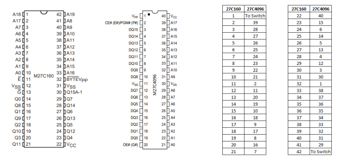
Here’s a breakdown of the pinouts on the 27C322, 27C160, and the 27C4096.
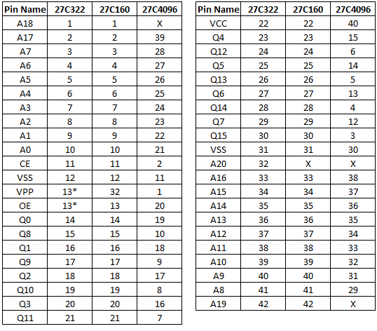
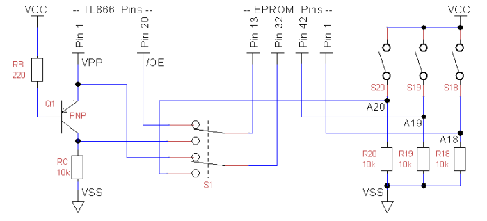
Remember, the 27C4096 is the chip we’re going to tell the TL866 we’re programming. The X’s signify an address pin that goes unused on that chip. We’ll be adding three switches to manually control these pins – A18, A19, and A20. You’ll note that the 322 and 160 share every single pin, except that 160’s don’t utilize A20, and the VPP and /OE pins are a bit different.
According to the datasheet for the 27C322, pin 13 (or /GVpp as it’s defined) combines the /OE (output enable) pin and the VPP (programming voltage) pins into one. The 4096, however, keeps these pins separate. This isn’t too much of a problem, though, if we take a look at the operating modes of the 322 we can see that we never really need the /GVpp pin to be anything but zero volts or the programming voltage.
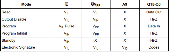
Here, VIL notates logic low, or zero volts. VIH is logic high, or anywhere between 2 and VCC + 1 volts (according to the datasheet). You’ll notice that the only mode that uses VIH is “Output Disable” which isn’t really used while programming the EPROM. So we only really need to switch pin 13 between ground and VPP (which means we can ignore pin 20 on the TL866 completely for programming the 27C322). Unfortunately, the TL866 switches VPP between the programming voltage and VCC voltage, so we need to add a bit of circuitry to change that VCC to GND.
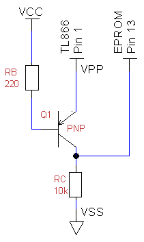
The PNP transistor above conducts when the emitter voltage is greater than the base voltage. During programming, the VPP pin from the TL866 applies the high programming voltage. When this happens, current flows through the base resistor (RB), and pulls pin 13 on the 27C322 to VPP. Then, when the VPP pin on the programmer drops to VCC voltage, the base current drops and the transistor stops conducting. This causes pin 13 to be pulled to VSS through the collector resistor (RC).
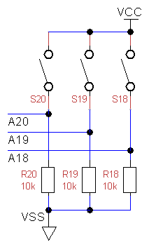
Now, taking care of the extra address pins is just using simple switches with pull-down resistors.
With this extra circuitry, we can make a standalone 27C322 adapter for the TL866. However, if you check that table again up at the top, you should’ve noticed that the 322 and 160 (and by extension, the 27C800 and 27C400) share a lot of common pins. The only real difference is which pin is used for the programming voltage – pin 32 on the 160 is the VPP pin, but on the 322 this is the A20 pin. We can easily reroute this using a double-pole-double-throw switch.
So with the extra circuitry, we now have our finished product, capable of allowing the TL866 to program 27C322’s, 160’s, 800’s, and 400’s.
Standalone 27C160, 27C800, 27C400 Programming Adapter
This is an older design I made that only programs 27C160’s, 800’s, and 400’s. It’s a lot simpler to understand, and doesn’t require the need for a DPDT switch or PNP transistor.
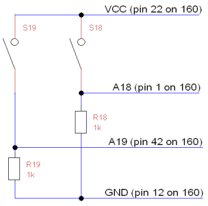
In order to program the 160’s, we’ll need to reroute the pins on the 160 to match the pinout of the 27C4096, which the TL866 supports. Here’s the pinouts of each of the chips from their datasheets, and the rewiring you’ll need to do.
Pin 1 (A18) and pin 42 (A19) are not available on the 4096, so they will go to the switches that will turn the two address lines to 1’s or 0’s. Here’s a schematic of how you’ll need to connect them to switches using a pull-down resistor.
Simple enough, right?

[…] 27C322/160/800/400 Programming Adapter (TL866) […]
LikeLike
Hello! Do you have any idea if this adapter will work with an old Needham’s PB-10 burner for 27C400 eproms? There was an original adapter called the “Needham 400”, but I can’t find any info about it. I’m assuming it should be the same?
LikeLike
Not sure to be honest, but if it can burn a 27C4096 and has a way to ignore Device ID, it should work fine!
LikeLike
The Zelda hack goddess of wisdom is a 1.5Mb rom 16Mb in Size
Should I use Lunar expand to make this in to 4 1Mb chunks?
Only I use spit the rom in 3 parts and burnt the rom to the chip only to find it didnt work 😦
LikeLike
Yeah, you can expand the file to be a full 2 MB, then split it into four 512 KB sections to program in the four banks on the 27C160.
I did a brief check on the ROM, I think I found it online. Did you apply the patch to a Link to the Past ROM? And did you test it in an emulator first?
LikeLike
[…] adapters, and can sell them to you over on my store page, or you can make your own, as I provide schematics for them. I’ll go over which one you might need for your project later […]
LikeLike
Thank you for making this excellent adapter! I’m hoping to be able to use it on a TL866II to program a MX29F1615PC, which is a 42-pin DIP EEPROM (2Mx8 or 1Mx16) that I believe is pin-compatible with the 27C160 (other than VPP needs to be 10v for the MX29F161PC). Do you have any experience programming this part?
I’ve tried the following (from Linux), but get “This chip can’t be erased!”:
minipro -p AM27C4096@DIP40 -o vpp=10 -o vdd=5 -o vcc=5 -y -E
If I try to program, I get “Verification failed at address 0x0000: File=0x11, Device=0x00” with:
minipro -p AM27C4096@DIP40 -o vpp=10 -o vdd=5 -o vcc=5 -y -w rom.bin
I always see the following, which might not be a problem:
“WARNING: Chip ID mismatch: expected 0x1001900, got 0x0000 (unknown)”
LikeLike
Hmmm, I’ve never used any of these before, but I imagine it has something to do with how you program it compared to the 160. EPROMs and EEPROMs are interfaced in different ways, and it looks like there’s a table of commands you need to enter to do specific tasks, like erasing and writing. Normally, you can only erase a 160 with UV light, which is probably why you get an erase error message.
LikeLike
Thank you for your help. Now that you’ve explained it, it makes sense that the “This chip can’t be erased!” is because the AM27C4096 is not an EEPROM. I guess I’ll need to figure out if I can tell minipro that the pinout is compatible with the AM27C4096@DIP40, but programming protocol is similar to an EEPROM (though with 10V VPP). I wish there were a little more documentation on what the TL866II Plus does with message packet arguments.
LikeLike
Hmm yeah I’m not sure, if there is a way I’ve never seen it! But if you come across it that’d be interesting for me too haha. Good luck 🙂
LikeLike
Hi, sorry, didn’t think that option would be too popular! Haha. Here it is, let me know if you need more info.
LikeLike
Hello,
I am using the adaptor from this guide with a 27c322. I keep getting a programming failed message on both of my eeproms. I keep erasing the chips and starting over. Is there a setting in the software I am missing? Any help you can provide would be great.
LikeLike
Just make sure the settings look exactly the same as the pics in this guide and you should be good as far as that’s concerned. Let’s try to narrow down the issue:
What error do you see?
Do you get the error immediately when trying to program, or does it happen after a bit of programming?
Do the chips pass a blank check before you hit program?
Do you have more than 2 to try out? The parts are notorious for having defects.
Is your switch in 27C322 mode, and the chip in the correct orientation?
Also, when did you order the adapter board?
LikeLike
olá!
Como faco para dividir as roms
LikeLike
Hey there! I should add this to the article – if I’m not using SNES ROM Utility to split the files, I use this tool: https://www.romhacking.net/utilities/812/
LikeLike
Hey there, when you load the chunks into Xgpro, is it normal for the bytes to be reversed?
[img]https://i.imgur.com/f9ThQLE.png[/img]
LikeLike
Hm, doesn’t usually happen that way for me. Are you sure the ROM didn’t have the bytes swapped?
LikeLike
Literally just followed the steps here. Started with a patched SMC file, verified checksums, removed header, split with ROM utility, and that’s what I see when I open the first chunk in Xgpro.
LikeLike
Sorry, by “here” I meant in your repro tutorial. I’m having difficulty with a repro board I had manufactured, and unless I’ve got an entire batch of bad logic IC’s, or there’s a manufacturing problem with the PCBs, then theres something wrong with the way I’m writing my EPROMS and I can’t figure it out.
LikeLike
What does the ROM look like before you do all that? Try removing the header, then loading it in (before splitting) to see if it’s originally swapped.
Can you take a screenshot of the entire xgpro window?
LikeLike
There’s no “Reply” link on that last post? WordPress be weird! 😛
Anyhow, I got to the bottom of it. The DIP switch on the stupid adaptor board I bought works completely backwards, ***and contrary to its silkscreening***!!!!! I.e. ON = 0, and OFF = 1 for A18~20
The only way I was able to verify this was by having someone with a “proper” 42-pin compatible burner write my ROM to a chip, verify that it worked, and send me the working EPROM so I could do a comparison.
Really frustrating, but glad I got to the bottom of it, and can move on with my project! 🙂
LikeLike
You know, thinking back, someone had that same problem like a year ago haha
Well at least it was an easy fix!
LikeLike
An easy issue to fix, yes, but many hours chasing ghosts trying to find it! 😭
LikeLike
i get “over-current protection action”when i try to burn a 27c400, any special settings on the voltage side im missing?
LikeLike
Make sure you have the 400 (40 pins) in the 42 pin socket such that pins 1 and 42 on the socket are empty
LikeLike
Thanks, it worked now
LikeLike
Hello,
Thank you for your response. I have checked my settings and rechecked. It starts to program, but then it stops. Today, after trying to erase both, a couple of banks on both have a bit of data on each that won’t erase. I am thinking both are bad…
For instance, one 27C322 has one bite that will not be erased on bank three, but even when trying to program bank one it fails at 12.5%. It says programming flash failed. FYI, I ordered the board two weeks ago with the SA-1 adapter through your etsy. All I have is two chips I ordered from Ebay, “New” from China. If you have another contact, I can send you a screenshot and a picture of my board. everything looks good (soldering job, switches, chip orientation.)
Thanks
LikeLike
If you’d like to email me pics, my email is nick@mousebitelabs.com, but it does sound like defective 27C322s, especially if you’re able to program them a bit. Do both fail at the same place, 12.5%? There *could* be a bad solder joint if both chips fail in the same way.
I think it’s basically impossible to get true “new” chips, you especially can’t trust the listings to be accurate haha. They might look new, but a lot of times they’ll take the old chips and print over them with brand new ink so they look new. It’s called “blacktopping”
What you could try is erasing them in the UV eraser for half an hour, then do a blank check. If they’re not blank, try another 15 minutes, and re-blank check. If after a few times they don’t fully erase, then yeah I’d guess you’ve got some with bad sectors.
You can ask for a refund from the seller, in my experience they’ll usually give you a refund (sometimes they ask you to send a picture of the chips “destroyed’ which is funny lol)
LikeLike
I have practically obliterated a 27c801 recently and managed to salvage it after a couple of attempts under UV light. Prior to the second exposure, I had to thoroughly clean the window with isopropyl alcohol as I had placed a reflective adhesive on it beforehand.
It’s possible that you’re unable to perform a full erase due to a partially obfuscated UV window on the eprom.
LikeLike
Hi, i dont have the adapter to program 27c322 in tl866. Is possible to put the eprom in a protoboard and wire all the connetions? how it can be done? thank you
LikeLike
You can but it’ll be a hassle. You can follow the schematic on this page to make your own
LikeLike