Note: This is an outdated project. I’m working on a cheaper bluetooth controller. A lot of information in here will carry over to the new tutorial, though, so feel free to familiarize yourself.
I was playing Mega Man 2 in my living room on my NES, sitting just far enough away from the console that the cable for the controller was taut. Nearly pulled the NES off of the table. A problem from a simpler time, I thought. I could get this to be wireless, surely!
So I got to looking online for solutions.

Well… I found this. But I’d rather make my own. It’ll be a fun little electronics project!
Not counting the 3D printed case and smaller parts like resistors and capacitors, I spent overall about $40 on this project. Here’s what we’ll need:
1) One NES controller
2) Two ATMega328 processors (and an accompanying Arduino board to program them)
3) One wireless transmitter and receiver pair (about $10)
4) A shift register (such as the CD4021, which just so happens to be used by the controller)
6) Lithium ion battery (I used a 330mAh battery, but even something as small as 100mAh will still get you ample play time – make sure it can fit in the controller!)
7) Protoboard
8) A switch – I used these, but you can use your own and drill a hole in the model for it
9) Miscellaneous components (resistors, capacitors, 16MHz crystal oscillators, and LEDs)
You’ll also need access to a 3D printer. If you’re still in school, check to see if you can get 3D printing services. If they don’t, you can send it out to get it made on some website, or you can order one from me! Just email me (thepoorstudenthobbyist@gmail.com) with the model you want, and I’ll get back to you on a price and time frame. I might even do some custom orders, if you ask nicely, and don’t have outlandish requests. Currently I can only print in white, though. But you can paint it if you wanna. Here’s the Thingiverse entry for the controller and the receiver.
I bought most of my supplies on eBay from China. It takes a few weeks to get here, but the savings can be great for the simpler things. As a quick comparison, you can buy a single ATMega328 on Amazon, Adafruit, or Sparkfun for upwards of $5, or you could buy a five pack from China for little more than $10.
The transmitter and receiver seem to be best available at Sparkfun, so you might want to consider buying the battery and battery charger from there as well to cut down on shipping costs. The only part of this tutorial that would be slightly different is for the battery charging circuit.
A note on the batteries – make sure your battery will fit inside the controller. A 2000mAh is awesome, but complete overkill. And definitely won’t fit in the controller I’ve designed. Keep it under 500mAh and you should be good. The space provided in the controller is about 1″ x 1.5″.
Enough boring exposition – let’s kick off this journey by learning how the controller actually works. If you’re so inclined to skip the prototyping steps and just build the controller, skip to the “Expanding the Transmitter Test Unit” section.
How the NES Controller Works
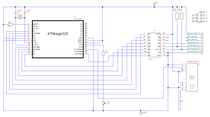
The NES controller is surprisingly and satisfyingly simple, actually. It uses a single IC – the CD4021. Just a simple shift register. The schematic for the controller is below.
Note: When figuring out which wires correspond to which pins on the controller port, do NOT trust any color diagrams you find online. Mine did not match the one I found, and it turns out Nintendo changed the convention a few times. The easiest thing to do is use a multimeter and figure out which wires go where.

If you are wondering, I use TinyCAD for schematic drawing.
So each button on the controller corresponds to a different digital input into the shift register. The NES sends a pulse through the latch wire (on the P/S pin) at a rate of 60 Hz, or once per 16 ms. When the shift register receives this pulse, it takes the states of the buttons and sends it through pin 3 (Q8, labelled as “Data” above) as serial data. The rate at which this data is sent is determined by the clock speed, on pin 10 (approximately 83 kHz, sent from the NES). The NES will take this serial data from the data wire. The data is analyzed from the pulse train, the state of each button is determined, and the game takes care of the rest from there.
 A timing diagram for the NES and the controller. The NES sends the latch and clock pulse trains, the controller sends the data pulse train. In this example, the B and Left buttons are pressed. Note that a pressed button is represented by a low signal.
If this explanation isn’t sufficient enough, here’s a more in-depth explanation of shift registers. If you know how they work, you can skip ahead.
Each button is either on or off. This is classically defined as a 1 or a 0, however in the case of the controller, they decided it was easier to set on as a 0 and off as a 1 (a “1” state is 5V, a “0” state is 0V). This achieved using the resistors R1 through R8 (which are known as “pull-up” resistors, because they pull the signal up to 5V) which are paired with the buttons. When the button is not pressed, the circuit is not completed, forcing the pin on the shift register to 5V from the supply. When the button is pressed, the pin is grounded, forcing it to 0V.
The states of these 8 buttons, reading either 5V or 0V, are collected by the shift register. When the P/S pin is activated by the NES using a small pulse, a snapshot of the button states is taken, and is fed through the serial output as a string of 8 bits (or a byte). This string of 8 bits would be represented by an oscillating square wave, if you were to look at the signal on an oscilloscope. Once the 8 bits have been fed through and read, the NES sends the pulse again to take the next snapshot. So, if you were playing Super Mario and you were running to the left (so holding the B button and the left D-pad), the byte would read 10111101.
Make sense? It’s not complicated once you get the hang of it. It’s worth mentioning that the data going into the shift register (8 separate pins) is known as “parallel” data, and the data coming out (one single pin) is known as “serial” data. This is a good idea, because otherwise there would be 7 more pins coming out of the controller port if they decided to go only the parallel route.
So here’s how our overall system will work. The NES controller will send its button presses to the digital pins of the transmitting ATMega328. This transmitter will send the button presses wirelessly, as a byte, to the receiving ATMega328. This receiver will analyze the byte, determine which buttons were pressed, and mimic those button presses to the shift register through eight digital output pins. The NES will then read the parallel data on the shift register and receive it as serial data as it would a normal NES controller.
Simple, right?

If this picture doesn’t make it look simple, nothing will.
The Beginnings of the Receiver
Now that we know how the controller works, we can begin to make the receiver end of the wireless controller. You’ll need a CD4021 shift register. They’re widely available today, even though they’re 30-something years old. I found a bunch at my local electronics hobby shop, or you can buy them online for about $0.50 (I recommend eBay if you don’t mind waiting for things from China – I got about 10 for a buck). The Arduino IS capable of sending serial data to the NES, which would eliminate the need for this external shift register, but this way to me is easier to program and troubleshoot without more expensive equipment (like an oscilloscope).

The CD4021 chip makes this baby hum. It’s not humming a very complicated tune, either.
Now that we have the shift register, find ten resistors to use as pull-ups (shown as R1 through R10 below). I used a few 10kΩ resistors myself, since I had a lot lying around, but most sizes between 1kΩ and 50kΩ should work fine, since we’re not using current to control our ATMega. You’ll want to keep the resistor size above 1kΩ, as lower resistances might pull too much current from the NES. The wiring schematic I used is shown below.

R11 is connected to a pushbutton, used to start the program used for debugging. In the final product, this button will not be used. I used pins 2 through 9 to correspond with the buttons shown in the previous post. Use the table below for reference.
| Arduino Digital Pin | 4021 Pin | 4021 Pin Name | NES Button |
|---|---|---|---|
| D2 | 7 | P1 | Right |
| D3 | 6 | P2 | Left |
| D4 | 5 | P3 | Down |
| D5 | 4 | P4 | Up |
| D6 | 13 | P5 | Start |
| D7 | 14 | P6 | Select |
| D8 | 15 | P7 | B |
| D9 | 1 | P8 | A |
The NES reads the button states in this order: A, B, Select, Start, Up, Down, Left, Right. It’s important that we use this order of buttons in our program and keep the pins consecutive. This will become apparent later in the tutorial.
I’ve cut off a controller port from our controller, and soldered new wires to the small ones to put in a breadboard.

What the board will look like after wiring up the controller port. The three LEDs are from another project, and it is not necessary to use them.
After connecting everything shown in the schematic above, you can run a test program. For my program, I simply flashed the start button on and off every two seconds. The code I loaded into the Arduino to test this is below.
NOTE: Be sure to disconnect the USB cable from the Arduino when plugging it in to the NES – otherwise power will backfeed into the NES from the controller connector. When you turn the NES on, the Arduino will turn on from power coming through the 5V pin on the connector.
//Presses start button on and off every two seconds
 int right=2;
 int left=3;
 int down=4;
 int up=5;
 int start=6;
 int select=7;
 int b=8;
 int a=9;
 int button=11;
 int ledpin=13;

void setup(){
 pinMode(right,  OUTPUT);
 pinMode(left,  OUTPUT);
 pinMode(down,  OUTPUT);
 pinMode(up,  OUTPUT);
 pinMode(start,  OUTPUT);
 pinMode(select,  OUTPUT);
 pinMode(b,  OUTPUT);
 pinMode(a,  OUTPUT);
 pinMode(button, INPUT);
 pinMode(ledpin, OUTPUT);
 digitalWrite(right, HIGH);
 digitalWrite(left, HIGH);
 digitalWrite(down, HIGH);
 digitalWrite(up, HIGH);
 digitalWrite(start, HIGH);
 digitalWrite(select, HIGH);
 digitalWrite(b, HIGH);
 digitalWrite(a, HIGH);
}

void loop(){
 //Wait til button is pressed
 while(digitalRead(button)==LOW){
  digitalWrite(ledpin, LOW);
  delay(100);
 }
 while(1){
  digitalWrite(start, HIGH);
  digitalWrite(ledpin, LOW);
  delay(1000);
  //Flash led connected to pin 13, and emulate start button press
  digitalWrite(start, LOW);
  digitalWrite(ledpin, HIGH);
  delay(1000);
 }
}
Pop in your favorite game, and see the game respond to your start button presses! Now if you want, you can program in other button presses. You can even, oh I don’t know, program it to run the first level of Super Mario Bros.
While waiting for my wireless dongles to come in the mail, I made this neat little program. The LEDs on the breadboard were used for debugging. Red LED indicates pushing the A button to jump, yellow LED indicates program is running in the main loop, and green LED was just to signify the end of the program.
This receiver will be modified before the final product, but it’s a good start for now. Let’s delve into the wonderful world of wireless wonders.
Preparing to Test the Wireless Communications
Now it’s time to try out your dongles (heh). The two devices I bought are very easy to interface with, especially with the VirtualWire.h library for Arduino that exists for many such devices. You’ll need to download and install this library to the Arduino IDE.
For this step, you’ll either need two Arduinos, or you could use an ATMega328 processor on a breadboard. I chose this path, since I only have an Uno at my disposal. But how do you use an ATMega on a breadboard, I hear you ask. Luckily, I have an answer for you in the form of a schematic.
 No way it’s that easy!
That’s all you need. Just connect your 5V and GND wires to a power source (I use the power pins on the Arduino board while prototyping). R1 holds the RESET pin high to 5V – this will keep the program running. X1 is a crystal oscillator, which drives the clock signal to the processor – I used a 16MHz crystal, which is standard for the 328. The crystal also needs two 22pF (or whatever you can get closest) capacitors for stabilization. The LED is just a power indicator.
AREF is the reference voltage used for scaling the analog inputs, and AVCC is used for the analog pin power. Since we won’t be using these pins, just tie them to VCC.
Note that the pin numbers don’t correspond to the pin names – for example, D0 (digital pin 0, or the RX pin) is pin 2. D7 is pin 13. In the future, be sure to connect to the correct pins.
But how do you put this code onto your ATMega without an Arduino? Simple. Just put the ATMega into the Arduino Uno and upload your program. Then, remove the chip and place it on your breadboard. You’ll want to be sure that you can easily insert and remove the processor at will, should you need to reprogram anything. You’ll also need to ensure you put the chip in with the correct orientation.
Most ATMega328s are preloaded with the Blink test code. Hook up an LED to D13 (pin 19) to check. If you get nothing, then program the Blink code into your ATMega and try again.
If the Blink code still isn’t working, try removing the two 22pF capacitors – your breadboard might have enough internal capacitance to keep the timing accurate, and the added capacitance might screw up the oscillator. You’ll need to add them back in if you plan on moving to a printed circuit board or a more permanent soldered protoboard.
Setting up the Transmitter Test Unit
I’m going to use this separated ATMega to drive the transmitter module. This is because we’ll want to read what the receiver is…. receiving… by using the Serial Monitor. So here’s how you’ll want to wire the transmitter side.

Again, pretty simple. Make sure you don’t flip the pins on the transmitter.
I’ve re-purposed some sample code I found online to test our setup. The code below will simply send an arbitrary number to the receiver. The receiver will be connected to our COM port to read through the serial monitor. It’ll only print the number if it receives it, because the VirtualWire.h library sends a check to the receiver, so you’ll know if it’s actually transmitting or not. Here’s the code that you’ll load into the ATMega of the transmitter.
// Transmitter Test Unit Code
 #include <VirtualWire.h>
 byte number=170; //Arbitrary binary number (10101010)

void setup(){
 // Initialise the IO and ISR
 vw_set_ptt_inverted(true); // Required for specific model, you probably don't need this
 vw_setup(4800); // Maximum bits per second recommended by manufacturer
}

void loop(){
 // Sends the binary number once every second
 digitalWrite(13, true); // Flash a light to show transmitting
 vw_send(&number, 1);
 vw_wait_tx(); // Wait until the whole message is gone
 delay(100);
 digitalWrite(13, false);
 delay(1000);
}
So you’ve got your breadboard transmitter. For testing purposes, as I mentioned before, I ran the power pins off of the 5V and GND pins from the Arduino Uno board. The data will still be transmitted wirelessly, they’ll just be pretty close to each other.
Setting up the Receiver Test Unit
The receiver is a bit more complicated than the transmitter. But at least we can still use the Arduino Uno, making it a bit easier to wire up. I’d suggest using the same Arduino from earlier, and keep your shift register wiring, because you’ll need it later. Here’s the schematic.

Not too bad. The shapes and relative positions of the pins on the receiver that you see are accurate to the actual model. The LEDs on the shift registers were added for troubleshooting later.
And here’s the code you should upload.
// Receiver Test Unit Code

#include <VirtualWire.h>
byte number;

void setup()
{
 Serial.begin(9600);
 vw_setup(4800);     // Maximum bits per second recommended by manufacturer
 vw_rx_start();       // Start the receiver PLL
 pinMode(13, OUTPUT);
}
void loop(){
 digitalWrite(13,false);
 byte buf[VW_MAX_MESSAGE_LEN];  // sets variable for received message
 // VW_MAX_MESSAGE_LEN is equal to 80, it is a constant in VirtualWire.h
 byte buflen = VW_MAX_MESSAGE_LEN;  // sets maximum message length
 if (vw_get_message(buf, &buflen)){ // Checks to see if the message was received
 // and if it was within than the maximum length
  digitalWrite(13, true);
  number=buf[0];
  Serial.println(number, BIN);
 }
}
Load it up, make sure power is being delivered to your transmitter. Pull open the Serial Monitor, you should be getting a steady signal of “10101010”. If you’re not receiving this byte, make sure you have the baud rate set to 9600 in the Serial Monitor, make sure everything is wired up correctly and all the appropriate LEDs are on or flashing, and that you have the transmitting ATMega on the breadboard and the receiving ATMega on the Arduino.

Here’s my setup at this point. The transmitter is using the standalone breadboard with ATMega, seen on the back left. The receiver dongle is on the breadboard on the right, and the Arduino with receiver code is on the front left. It is connected via USB to my computer so that I can read the received data through the Serial Monitor.
Expanding the Transmitter Test Unit
Once you’ve verified that the receiver is getting the test number 10101010, it’s time to expand it to transmit the NES button presses. To do this, we’re going to emulate an NES with our microcontroller. As I discussed earlier, the NES sends out a signal through the latch wire, which is received by the shift register. The shift register then sends back the states of the buttons in the form of serial data at the rate sent through the clock wire.
You’ll need to take your controller cable that you cut up earlier, and extract the five wires coming out of it. I soldered on new wires and taped the bare wire, and then put them into the receiver breadboard. The power line should go to the 5V rail, the ground wire should go to ground, and I put the clock on pin 8, the latch on pin 7, and the data on pin 6.

The only real addition is the NES controller wires on the left.
Here’s the code you’ll need to load into your ATMega (it’s actually the final version of the code you’ll need).
// Final Transmit Unit Code
#include <VirtualWire.h>

int clock = 8;
 int latch = 7;
 int data = 6;
 int x;
 byte nespad = 0;

void setup(){
 // Initialise the IO and ISR
 vw_setup(4800);     // Maximum bits per second recommended by manufacturer
 pinMode(clock, OUTPUT);
 pinMode(latch, OUTPUT);
 pinMode(data, INPUT);

 digitalWrite(clock, LOW);
 digitalWrite(latch, LOW);

 Serial.begin(9600);
}
void loop(){
 digitalWrite(latch, HIGH);
 delayMicroseconds(12);
 digitalWrite(latch, LOW);
 // The Latch has now been sent, so send clock signal and read the button states
 for(x=0;x<8;x++){
  digitalWrite(clock,LOW);
  delayMicroseconds(4);
  nespad = nespad << 1; // Shift the bits of nespad to the left
  nespad = nespad + digitalRead(data); // Add the new pin state, either a 1 or 0
  digitalWrite(clock,HIGH); // Next button state is output to the data line
  delayMicroseconds(4);
 }
 digitalWrite(clock,LOW);

 digitalWrite(13, true); // Flash a light to show transmitting
 vw_send(&nespad, 1);
 vw_wait_tx(); // Wait until the whole message is gone
 delay(1);
 Serial.println(nespad, BIN);
 digitalWrite(13, false);
}
Load it up, be sure your USB cable is plugged in, and open the Serial Monitor. You should be seeing a string of 1’s when no buttons on the gamepad are pressed. Try pressing some buttons, and you should see some 0’s start to show up. It’s pretty fast, faster than the NES actually samples. This is important, as you’ll want to send the data to the receiver faster than the NES would sample it so that you don’t experience any missed button pushes or lag.
Expanding the Receiver Test Unit
Let’s add the same level of functionality to the receiver as we did the transmitter. Now, we’ll have a receiver that can extract data from the received number, and mimic the output of the controller onto the shift register of its own that will then be read by the NES. Remember those LEDs we added? This new code will allow you to see your button presses in real time, and will actually be the final version of the code to use in your receiver, just like the transmitter! Load this code up onto your receiver ATMega.
// Final Receiver Unit Code

#include <VirtualWire.h>

byte number;

int A = 9;
int B = 8;
int Select = 7;
int Start = 6;
int Up = 5;
int Down = 4;
int Left = 3;
int Right = 2;

int x;

void setup(){
 Serial.begin(9600);
 vw_setup(4800);     // Maximum bits per second recommended by manufacturer
 vw_rx_start();       // Start the receiver PLL running
 pinMode(13, OUTPUT);

 pinMode(A, OUTPUT);
 pinMode(B, OUTPUT);
 pinMode(Up, OUTPUT);
 pinMode(Down, OUTPUT);
 pinMode(Left, OUTPUT);
 pinMode(Right, OUTPUT);
 pinMode(Start, OUTPUT);
 pinMode(Select, OUTPUT);
}

void loop(){
 digitalWrite(13,false);

 byte buf[VW_MAX_MESSAGE_LEN];  // sets variable for received message
 // VW_MAX_MESSAGE_LEN is equal to 80, it is a constant in VirtualWire.h

 byte buflen = VW_MAX_MESSAGE_LEN;  // sets maximum message length

 if (vw_get_message(buf, &buflen)){
  // Checks to see if the message was received
  // and if it was within than the maximum length
  digitalWrite(13, true);
  number=buf[0];
  Serial.println(number, BIN);
  for(x=0;x<8;x++){
   // This code reads each bit in the received byte
   // Depending on the bit, the corresponding pin, which is two places
   // ahead of the number in the loop, is toggled high or low
   if (bitRead(number,x)==1){
    digitalWrite(x+2, HIGH);
   }else{
    digitalWrite(x+2, LOW);
   }
  }
 }
}
Plug ‘er in to your NES through the severed controller port, and turn your NES on. It should turn your receiver on. Try turning on your transmitter as well, and push some buttons. Your LEDs on the receiver should start lighting up, and your NES should also respond. If not, double check to see if your transmit and receive LEDs are flashing on the transmitter and receiver. Also be sure to double check your wiring as well – it’s a decent expansion from before.
If you want to, after you’ve verified that all is working properly, you can pull your circuit off of the Arduino and onto its own standalone breadboard, like the transmitter. Here’s the circuit to follow.

Your final schematic for the receiver. If you’d like, you can remove the LEDs, if you are sure it works.

This is what mine looks like. For the final product, the LEDs will be removed and it’ll be a lot smaller than it looks like here.
Congratulations! You have a working wireless NES controller. You can stop now if you want. You’ll have ugly wire-laden breadboards lying around, but it’ll work. You could at least take your circuits off of the solderless breadboards and onto more permanent fixtures.
But if you want to make something a bit nicer and more portable, as an actual wireless controller would be, let’s add a rechargeable battery in the mix.
Making the Transmitter Battery Powered
For this part, I originally planned on buying a battery management IC and making circuitry around that. But as I looked further, it seems that Adafruit sells a nice little charging circuit for about the same as you would’ve spent on parts anyway. It also comes mounted with a USB port, and a standard connector to many rechargeable lithium ion or lithium polymer batteries (called the JST connector). I recommend the micro-USB version if you have an Android phone, as you’ll likely already have a ton of those chargers lying around. If not, you can also get the mini-USB version. Both are the same price, and have the same circuitry anyway. You’ll also need a battery, of course. I bought a 3.7V, 330mAh battery, since I figured that should hold a charge well long enough for many hours and the ATMega can work reliably on 3.7V. Also, it’s small enough to fit comfortably in the controller. This ran for a continuous 24 hours, meaning the circuit uses about 14mA. Adafruit has many different batteries to choose from.
An important note about these rechargeable batteries – make sure the battery you buy has protection circuitry built in to it. All the ones on Adafruit’s website has this. This will prevent the battery from becoming damaged from draining too quickly (such as from a short circuit) or from overcharging. Also, when picking your battery, make sure your charging circuit is correctly suited for the type of battery. The one I used, to which I provided links above, can charge 3.7V and 4.2V lithium ion/polymer batteries. Adafruit also has a great tutorial with more in depth information about batteries, if you’re interested. I’d recommend it, because lithium ion batteries have been known to explode and catch on fire without a protection circuit (seriously).
The wiring is extremely simple. Solder the battery leads onto the provided JST connector wires (make sure to get the polarity correct). Then connect the BAT pin on the breakout board to the power rail on your receiver, and the GND pin to the ground of the receiver. And that’s it! If your battery is already charged a bit, you should see your circuit working. If not, plug in your USB charging cable, and it should turn on.

This little baby will provide you with hours of NES gameplay. Note that’s a 900mAh battery, not a 300mAh. I was impatient and just took the picture with a battery I had lying around.
What’s next but to package it all up and put it in nice little cases? Nothing. That’s exactly what’s next. And last!
Finalizing the Packaging
What a journey, huh? We’re finally at the climax of this project – making it look oh-so-sexy. For this part, I first thought about just shoving everything into the controller by itself, but it was way too much stuff to just shove into that little thing. What I decided to do was make a 3D model of the back of the controller, and simply make it a bit deeper to put all the circuitry underneath the main PCB. This way, it would still feel like a normal NES controller but just a bit thicker, which is a welcome addition for me honestly (I have huge hands).

An isometric view of the front and back.
Here’s the Thingiverse entry for the controller and the receiver.
So I measured the locations of everything in the actual bottom of the controller. All those cylindrical things are for support for when you press the buttons on the gamepad. There is one that I think is used for keeping the cable in place, but since we won’t be using the cable anymore, I took out that support. That’s where the battery will go instead. On the bottom of the controller, I put a hole for the USB charging port. On the top near the middle, I put a square hole for the switch I bought, and two holes next to it for the charge LED and the power LED. And that’s all I changed!

Annotated elegantly, just for you, in MSPaint.
After I printed it out, I took an X-Acto blade and cut off all the support material and carved out the holes so that everything fit snugly (I purposely made it so that the holes would be smaller so I could finely tune how everything fit). You’ll have to drill your own hole for the switch, since there’s so many different ones you could use. Keep in mind that the controller back that I have is about 1/2 inches thick, so make sure your switch can fit.
Then I made a protoboard version of the transmitter, and cut it to fit between the support pillars. I put receptacles for the ATMega chip, just in case I needed to reprogram something. You also need to desolder the wires on the existing PCB, since you won’t be needing that cable. I pulled those wires down to the protoboard. Here’s the final circuit you’ll need to make for the controller, including the switch, the charging circuit, and the LEDs.
![]()
Not included is the NES PCB. I also added an antenna on the transmitter.
If you didn’t include the capacitors on the crystal oscillator on your solderless breadboard model, make sure to include them here! Another addition you’ll need to make is an antenna for the transmitter. It’ll need to be about 6 inches long for the 434 MHz transmitter. Make it into a coil shape to minimize real estate (I took a wire and wrapped it around a screwdriver). This shaped antenna also seems to transmit more effectively than a straight wire. I won’t get into antenna theory here, just trust me, it works better! Experiment with different shapes if you want to – that’s how you learn.

Beautiful, isn’t it?
After I ensured everything was working correctly, I glued down the charge board, the LEDs, and the switch. I didn’t glue anything else down, just in case I needed to remove it or modify it later. I don’t recommend gluing the battery, either. I used Loctite superglue that I got on Amazon.
Put the controller back together, and great! You’ve got a nice looking and comfortable wireless NES controller! Now we’ll have to package up the receiver, and we’ll finally be done. Here’s what the model looks like.

Time to go out with a very boring rectangular prism.
Again, here’s the Thingiverse entry for the controller and the receiver.
That’s my receiver. Deal with it. I had a bunch of 5cm x 7cm protoboard lying around, so I made a nice little 5cm x 7cm box to house it. It fits fine, juts out a bit though. I figured it be easier to make with more space. Once again, here’s the circuit to follow for the receiver. It’s almost exactly the same. Just remove the LEDs, and add a 6 inch antenna. Unlike the previous antenna, this one should not be coiled up. You can just stuff it into the box. Keep it as straight as possible, but don’t worry if you have to curve it a few times.
 I’m running out of things to say on these pictures.
For the points of connection to the plug, I just soldered five wires sticking out of the top of the board. Then I stripped the wires coming out of the plug. I put the board in the box, then put the plug into the case on top of the board (you might have to cut out the hole a bit for it to fit nice and snug). These wires coming out of the plug are pretty thin, so I also soldered extra wires onto them and covered them up with electric tape. Or you could be hardcore and use heat shrink.

It’s a tight fit. And it’s ugly. But it works! Note the antenna shape – it’s not coiled tightly.
I glued the LED to the hole, and plugged in the receiver to test it out. Verify all works well, then put the top on. I opted to glue mine together, because I like taking risks. I’d recommend maybe gluing only a few points on the receiver initially to keep the top on, but make it easy enough to open it up to fix anything you might need to fix.
When you’re done, you should have a nice looking, functional, homemade wireless NES controller!

What a beautiful isometric view of such a lovely product!
Final Words
Well, it’s been a long time coming, but we’ve finally finished our wireless controller! We learned how the controller works with shift registers, learned how to use the ATMega328 processor off the Arduino board, and learned how to interface wirelessly between processors.
Note that this controller works best when you have a clear line-of-sight from the controller to the receiver. I’ve had a few situations where if I sit just right with enough obstructions, communications could drop momentarily. But these were very few in number, and only when I tried really hard to screw it up. What do you expect from such inexpensive wireless modules? For the price and simplicity, this system works very nicely.
If you have any questions about this project, or you want to order these 3D prints directly from me, feel free to email me at thepoorstudenthobbyist@gmail.com. Stay tuned for more electronics tutorials!

Hello, Nick! How are you? I hope everything is alright. I’m Dan, from Brazil, we’ve talked a couple of times through email in the past. Finally, I was able to do wireless communication between a Sega Master System controller and the console. For this, I had to use the NRF24L01 module. But it’s working very well for me. I want to thank you for your help in the past. You have even suggested using a multiplexer. But it was not necessary. It works on Atari as well. The Atari controller has the same operation of the Sega Master System, the difference is that it only has a button.The Sega Genesis console, known here in Brazil and other places like “Mega Drive”, is a bit different controller. But I already know how I can do the same thing I did for the Sega Master System. I already have a sketch also for the SNES, but I do not have one now to test. That same SNES sketch can be adapted to the NES as well. So, any new project to show us soon? Best Wishes.
LikeLike
Hey Dan! Good to hear from you again. Glad to hear you got it working! I do remember finding out recently that the Sega controllers work with Atari games because they use the same protocol and button layout. Very convenient.
I’ve been focusing mostly on the SNES reproductions, but I do have parts and a few designs saved for a true Bluetooth controller like yours. I don’t think they’re the same modules as you’re using, but I can’t remember what the exact part number is. I need to find them again. I also plan on making my own PCBs for them! I have a wireless SNES controller that I made as well, using the same RF modules as this entry, but I have the same problems with it as I did with the NES ones – line of sight and range issues. Upgrading to bluetooth should fix this.
I also have a handful of projects that I’ve completed, I just haven’t documented at all. They’re not really Nintendo-related, and they’ve been collecting dust on my desk for a long time now, so I’m not sure when/if I’ll ever get around to putting them up here. My list for SNES and NES reproductions is so huge already!
LikeLike
Hello! The include directives in code blocks are incomplete, probably because wordpress stripped things between angle brackets.
LikeLike
Wow, thanks for that catch! I haven’t looked at that page in years, hahah. It should be fixed now.
LikeLike